
Process Improvement
Model-Based Inspection of Aerospace Parts
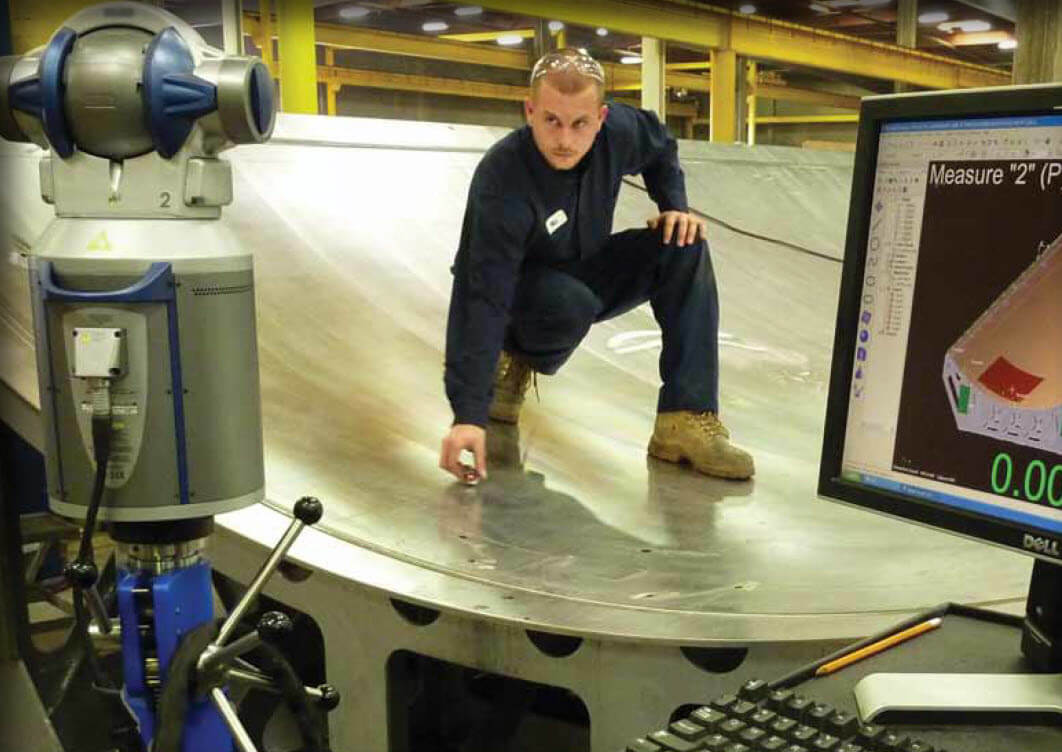
Using MBD for inspection speeds up the process and improves the surface quality of this commercial aircraft composite wing tool.
Leveraging model-based definition for quality assurance.
David Olson
Verisurf Software, Inc.
Anaheim, CA
Participants in the aerospace industry have substantially reduced if not eliminated the use of 2D drawings to convey dimensional and design intent information about parts and assemblies throughout the various stages of manufacturing. The industry has accomplished this via the widespread implementation of Model-Based Definition (MBD), particularly by OEMs and their first-tier suppliers. The use of a single authoritative digital source of part information has numerous systemic benefits, including:
- Eliminating errors that result from referencing an incorrect source.
- Making processes more efficient—no more searching to determine correct revision levels.
- Eliminating outdated drawings floating around the manufacturing floor.
- Eliminating discrepancies between the CAD model and 2D documentation.
MDB is having a particularly beneficial effect on quality, where Model-Based Inspection (MBI) is being implemented to provide faster and substantially more actionable information about the condition of parts and their manufacturing processes. MBI is allowing measurement tools and analyses to be more tightly integrated with every phase of manufacturing from design to final assembly. This not only serves to produce better manufacturing outcomes, but it also saves MBI users a great deal of time and money.
Origins of MBD
MBD has developed from the globalization of aircraft manufacturing and the extended product lifecycle of aircraft. In the past, aircraft companies were vertically integrated and manufactured most of their own aircraft components. Most had large machining centers and stretch-forming plants; some even had their own foundries.
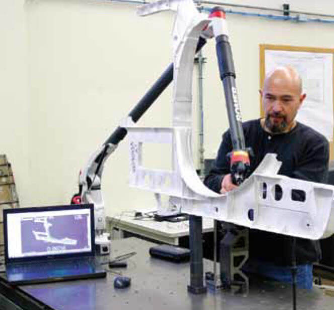
3D MBI data captured from an F-18 structural component at the US Navy’s NAVAIR Advanced Measurement Systems and Reverse Engineering Lab.
MBD, also known as digital product definition (DPD), is the practice of using 3D digital data (such as solid models and associated metadata) within 3D CAD software to provide specifications for individual components and product assemblies. The types of information included are geometric dimensioning and tolerancing (GD&T), component level materials, assembly level bills of materials, engineering configurations, design intent, etc. By contrast, other methodologies have historically required accompanying use of annotated 2D drawings to provide such details.
Boeing has been at the forefront of the MBD movement. Boeing D6-51991, Quality Assurance Standard for Digital Product Definition at Boeing Suppliers, calls for a dataset containing the exact solid, its associated 3D geometry and 3D annotation of the product’s dimensions and tolerances to specify a complete product definition. This dataset does not contain a conventional 2D drawing. MBD provides a single-source of definition, and it reduces conflict between CAD and paper drawings.
MBD Makes MBI Real
MBI is a very simple concept. It ensures that all of the information required to complete a manufacturing task, in this case, inspection, resides in one master source, the model, that can be readily accessed and understood by any person or tool that requires it. CAD-based inspection software has long been the most widely accepted tool for programming CMMs. The best of these programs provide an intuitive 3D environment that makes programs more efficient to write and inspection results easier to interpret. Even so, much of the information required to write a good CMM program, particularly GD&T, resided in sources that had to be accessed independently.
While some CMM software makes it possible to annotate models with GD&T data, it involves still another disconnected stand-alone process. Beyond that, the programmer must gather GD&T from annotated drawings. When the information is missing, undecipherable or incomplete, the programmer must make an educated guess based on his or her experience programming similar parts or contact the design engineer for clarification.
Within organizations that have committed to MBD, that information will be embedded in the model so that the design intent is absolutely clear. Furthermore, these organizations have made appropriate investments in people (training), processes (standardization) and technology (software, equipment, and infrastructure) so that MBD can be used across the boundaries that used to separate departments and serve as a Rosetta Stone that allows everyone to communicate effectively about their specialized and common objectives.
Once complete adherence to MBD has been established, everything else falls into place. There are very few capital expenditures required. After concentrating for a while on people and processes, companies that employ MBI will soon begin deriving exceptional advantages, not the least of which is reducing the tremendous costs associated with 2D paper drawings.
Eliminating Conventional Inspection Inefficiency
Going green is a wonderful thing, but reducing paper costs is far from the most compelling reason to purge 2D drawings from nearly every phase of manufacturing. Annotated paper drawings are sometimes hard to decipher, easy to damage or lose, increase the likelihood of manual data entry errors, and may not be the most current version. They also introduce a tremendous amount of cost. The conventional inspection process based on 2D drawings, still very much the norm at many manufacturing companies involves the following steps:
- Receive model from the customer
- Have CAD engineer or quality engineer make a blueprint
- Have approved by inspection department
- Make hard copies to be used in manufacturing and inspection
- Inspect and manually fill out an inspection report
For too long, manufacturing subdisciplines
existed in their own little kingdoms,
using tools and data sets unique to their own specialties.
Here is the breakdown of hours involved using a CMM to inspect a relatively small and uncomplicated aerospace part using the conventional 2D drawing process:
- Drawing creation (2-6 hours)
- Drawing on paper and printing (1–4 hours)
- Drawing based inspection—includes annotating drawings with GD&T information and writing an inspection program
(2–10 hours) - Ambiguity or uncertainty waste (1–100 hours)
The range of time presented here (6–120 hours) is broad because time costs in the last category (ambiguity or uncertainty waste) can easily be blown out of proportion when inappropriate or misunderstood tolerancing information results in bad parts that are accepted, or good parts that are rejected because tolerances are too inflexible. Both of these situations, however, happen frequently and they add hours to inspection processes.
Systematic Advantages
In addition to eliminating many of the disadvantages of conventional inspection protocols, MBI also introduces substantial advantages not only within inspection processes but also throughout all manufacturing processes. Measurement Device Independence: MBI need not be associated with any particular measuring device either in terms of device type or manufacturer. This means data collected using the most appropriate devices for the purpose at hand—hard gages, hand tools, height gages, CMMs, portables, laser trackers, laser radar, white light sensors, and spindle probes. Good MBI software can be programmed to integrate data collected from all of these sources, so users only need to be familiar with one software product. Measurement devices may also be used in combination to collect data for the same inspection task.
Measure Anywhere, Anytime: The universality of the measurement software along with the portability of the measurement tools means that a part can be measured anywhere and at any time—on the machine, next to the machine, or in the quality lab. Since the measurement software is based on the CAD model and sometimes embedded in a CAD or CAM environment, it is easy to create measurement subroutines for in-process gaging or complete inspection programs in the same environment used to create CNC manufacturing programs. By the same token, inspection data may be viewed within the CAM package to make toolpath adjustments based on graphical MBI feedback. This makes it far easier to troubleshoot first-piece manufacturing processes or refine them during prototype manufacturing.
Integration with Manufacturing Processes: Measurement tools aren’t just for inspection. The same model-based tools can be used for scanning artifacts for reverse engineering as well as locating components such as fuselage skins during assembly. Because the software is based on and integrated with the CAD model everyone in manufacturing including design engineers, manufacturing engineers, CNC programmers, and quality analysts have access to the same familiar operating environment. Laser trackers are an example of measurement equipment that may be tightly integrated with manufacturing processes. Airframe manufacturers frequently use them to locate components during assembly. The component is located, attached and then the location is once again confirmed. No further inspection is required at this point because an inspection step was an integral aspect of the manufacturing process.
Breaking Communications Barriers: For too long the various manufacturing subdisciplines existed in their own little kingdoms, using tools and data sets unique to their own specialties. When their work was done it was passed along to the next user in a form that would have to be translated into another unique set of tools and data sets, and so forth for the life of the program. Not only was this process terribly inefficient, but it also inhibited interdepartmental communication of information that could be used in partnership to greatly improve the total manufacturing outcome.
With MBD/MBI the primary tools and data sets are now identical and shared. Finally, everyone, for the most part, is speaking the same language. This makes it possible for design, manufacturing, and quality assurance folks to get together in front of the same graphical MBD information to quickly iron out ways to modify designs or incorporate less rigid true-position tolerances, so that the manufacturing process can make parts far more economically without sacrificing any of the critical dimensions necessary to the design.