
CAD Translation Validation for Manufacturing
CAD translation validation became an industry-wide requirement for commercial aircraft subcontract manufacturing via the Boeing DPD (digital product definition) D6-51991 standard. While translation validation software applications have other benefits and uses, the need for this quality control requirement remains mostly driven by the need for safety of flight for passenger carrying aircraft.
What is the Boeing D6-51991 standard?
The Boeing D6-51991 document is titled “Quality Assurance Standard For Digital Product Definition at Boeing Suppliers.” The latest revision N release, dated April 19, 2019, consolidates and replaces multiple Boeing requirements. The article outlines uniform specifications for supplier control of digital product definition data and specific requirements for CAD translation validation in section 8 and Product Acceptance Software (PAS) in section 3. This article will explore these two sections in greater detail.
Why validate CAD model translation?
Boeing and other aerospace manufacturers have stringent quality and safety requirements due to the critical nature of the components and systems used in aircraft. Inaccurate CAD model translations are a real issue and why Section 8 of D6-51991 exists. Here is a summary of why validation of CAD model translation is crucial in the manufacturing process.
- Safety and Regulatory Compliance: Aerospace products like commercial aircraft are subject to strict safety regulations. Any deviation from the original design, even minor ones in component dimensions or shape, can impact the safety and performance of the aircraft. To ensure compliance with these regulations, suppliers must validate CAD model translations to verify that the components they manufacture will meet the required specifications.
- Consistency and Quality Control: CAD models are the authority for designing and manufacturing aerospace components. CAD models must be translated accurately to maintain consistency and quality in manufacturing. Any errors or discrepancies in translation can lead to defects, inconsistencies, and quality issues in the final product.
- Fit, Form, and Function: The fit, form, and function of aerospace components are critical to success. Even minor differences in dimensions or shape can affect how parts fit together, potentially leading to assembly issues, reduced structural integrity, or operational problems. Validating CAD model translations helps ensure components fit together correctly and perform as intended.
- Traceability: In the aerospace industry, it’s crucial to have traceability and documentation throughout the supply chain. By validating CAD model translations, suppliers can provide evidence that the components they deliver are manufactured according to the specified design, which is essential for traceability and quality assurance.
- Risk Mitigation: For aerospace manufacturers, the cost of failures or quality issues can be substantial in terms of financial losses and safety risks. Validating CAD model translations is a proactive measure to mitigate these risks and prevent costly rework or safety-related incidents. To achieve these goals, Boeing and its suppliers employ Verisurf Validate software to verify CAD model translations are accurate and that the manufactured parts meet GD&T specifications. These processes help maintain the highest safety, quality, and precision required in the aerospace industry.
How CAD model translation validation works
Verisurf VALIDATE

CAD Model Validation for DPD Compliance1
1 VALIDATE is also an excellent tool for configuration control, model-vs-model comparison
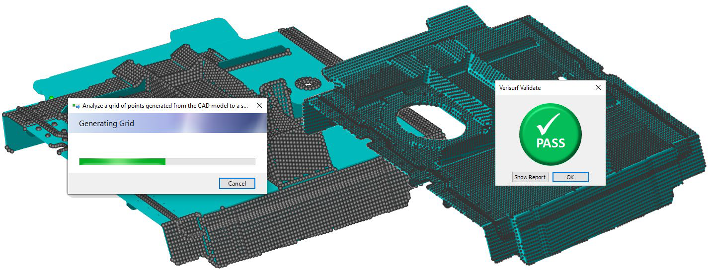
The Verisurf VALIDATE software application analyzes and verifies imported source, “authority” CAD models for Verisurf inspection. It provides comparison of the imported, “derivative” model to the original, native CAD source model, identifying any potential errors or distortions that might occur in the file translation process. The Verisurf VALIDATE optional product module includes fully integrated KUBOTEK KOSMOS Validate software and now comes included with the stand-alone version as well.
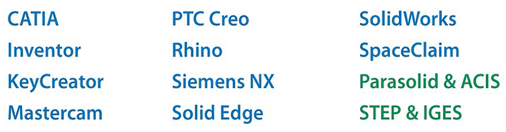
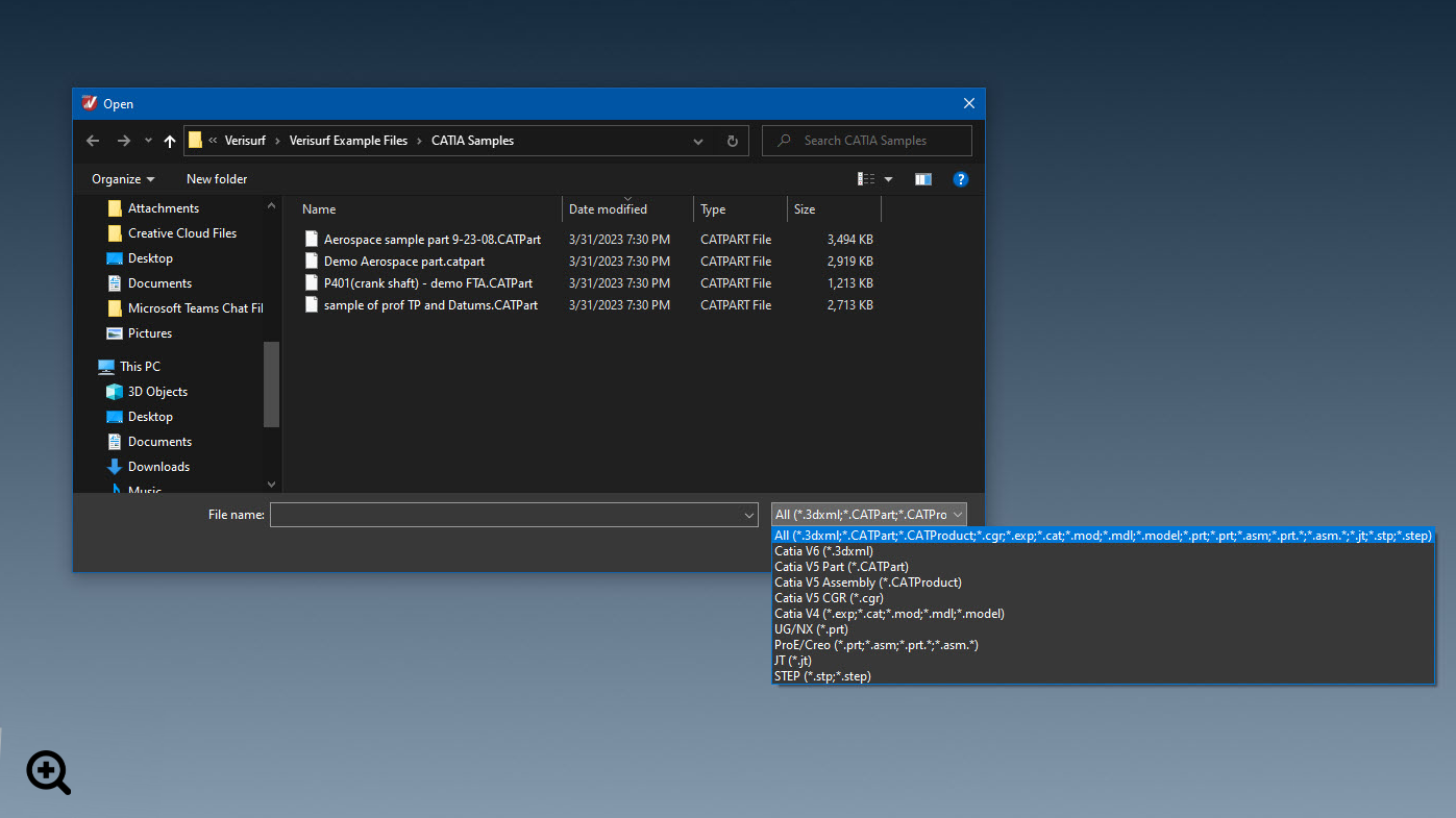
Verisurf is compatible with all native CAD model varieties.*
* Translator add-on required for some file formats
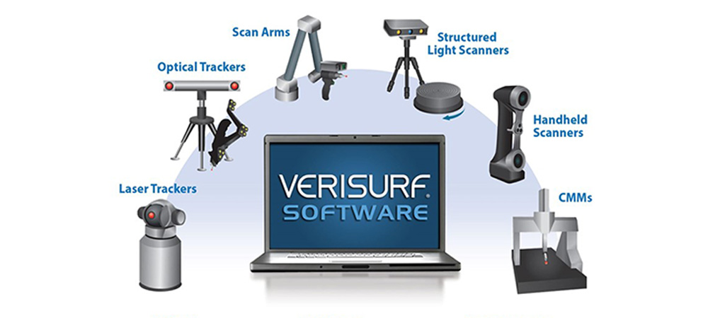
Verisurf is compatible with most 3D metrology devices.
1. Verisurf’s Integrated and Automated Validation Process:
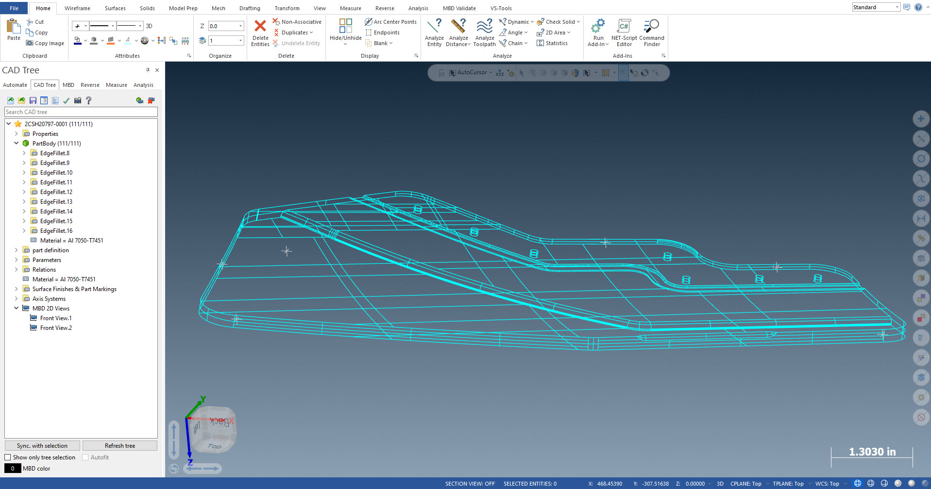
1.1. Import authority model into Verisurf
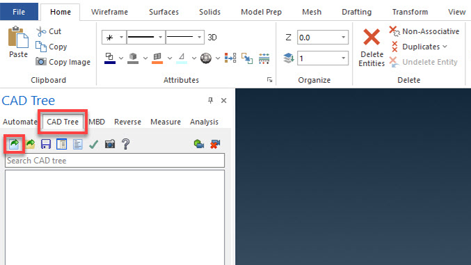
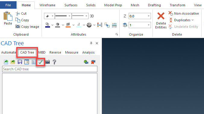
1.2. Launch Verisurf VALIDATE
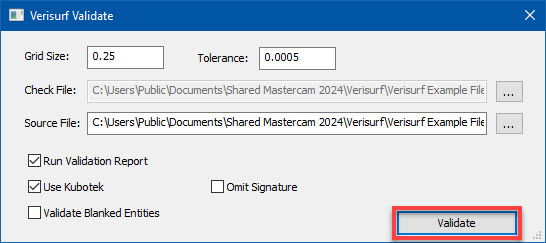
1.3. Select “Use Kubotek2;” check and adjust grid and tolerance settings if required; “source file” defaults to the authority model and optional “browse” button is available
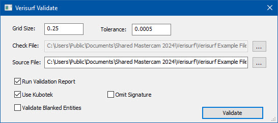
1.4. Initiate validation
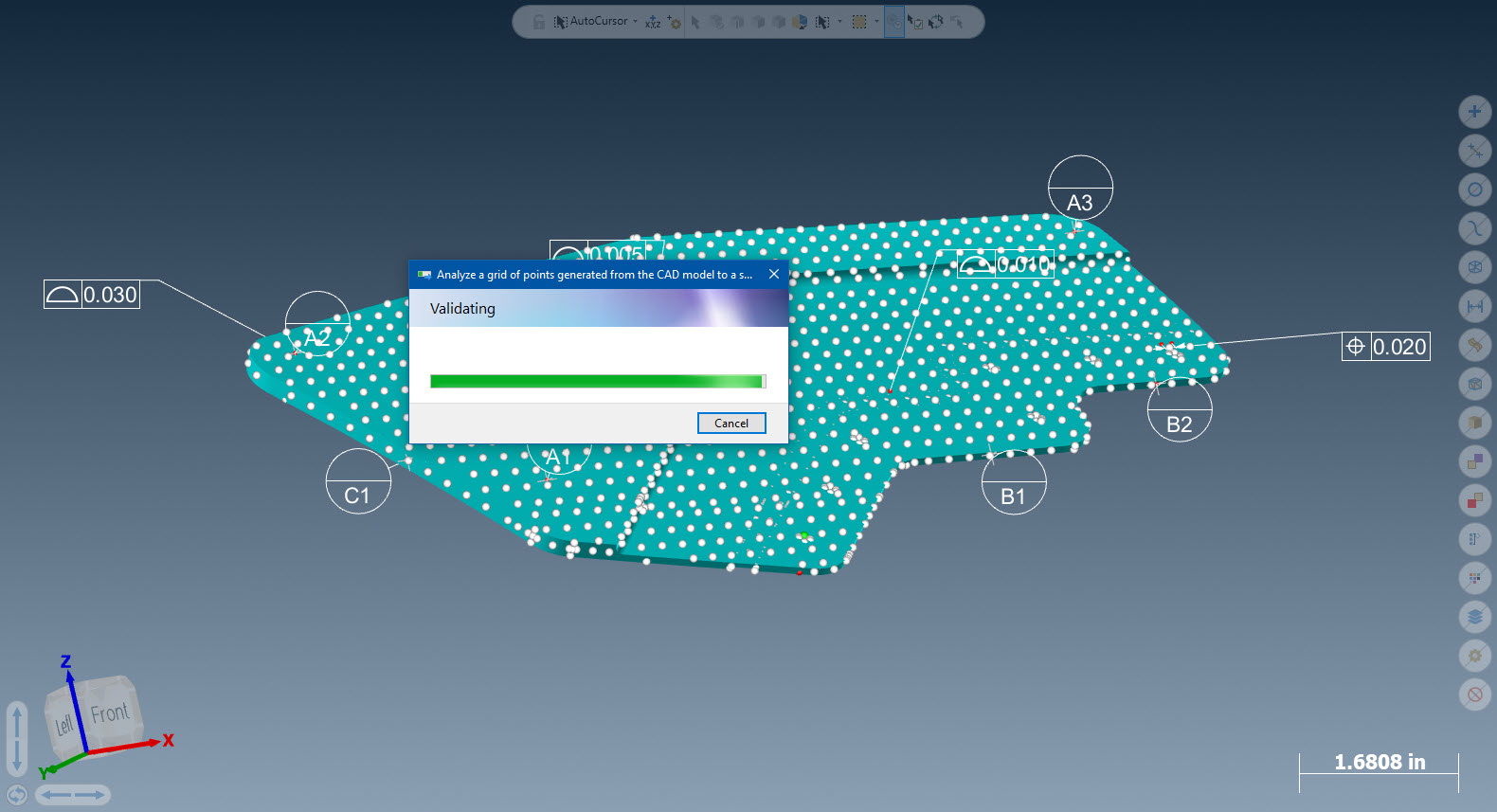
1.5. Validating – Grid points assigned to all surfaces of original authority model; points are then assigned and projected to derivative model, then analyzed for potential errors
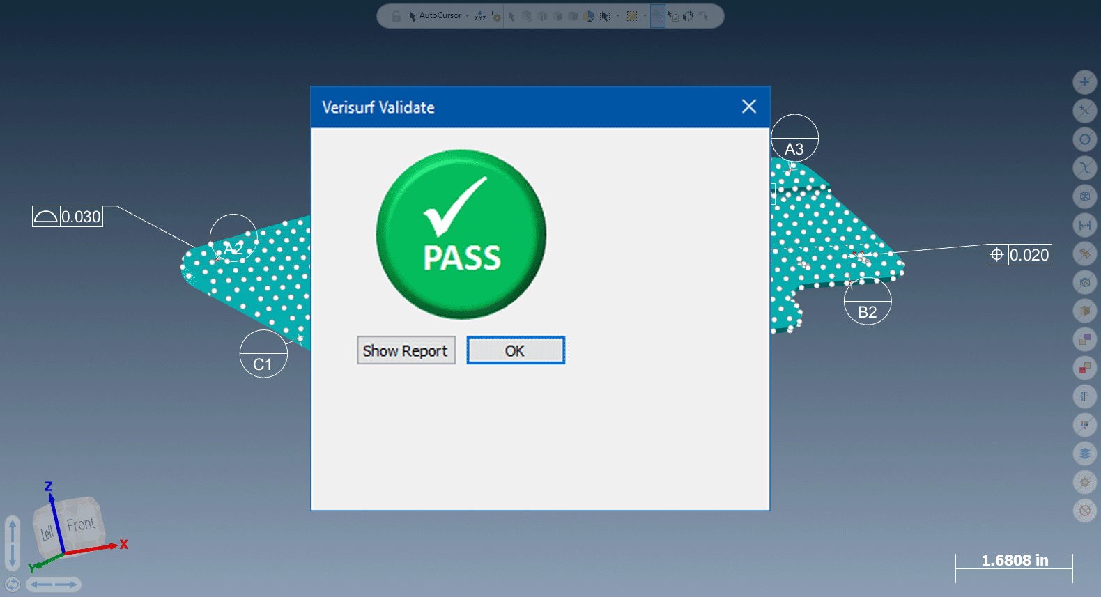
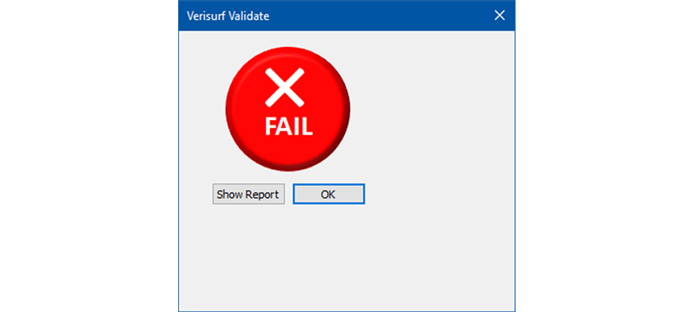
1.6. Pass/Fail result with “show report” option
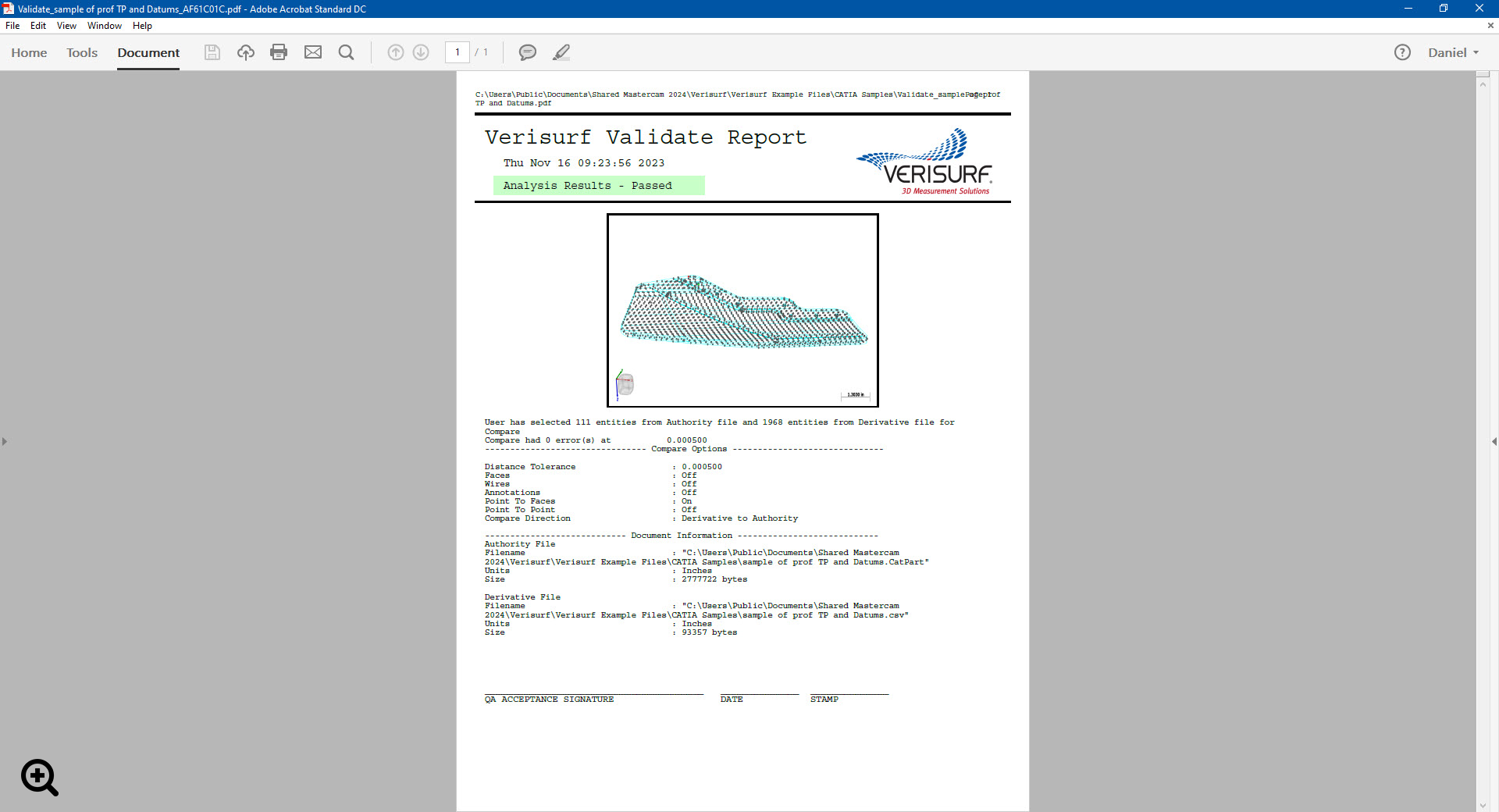
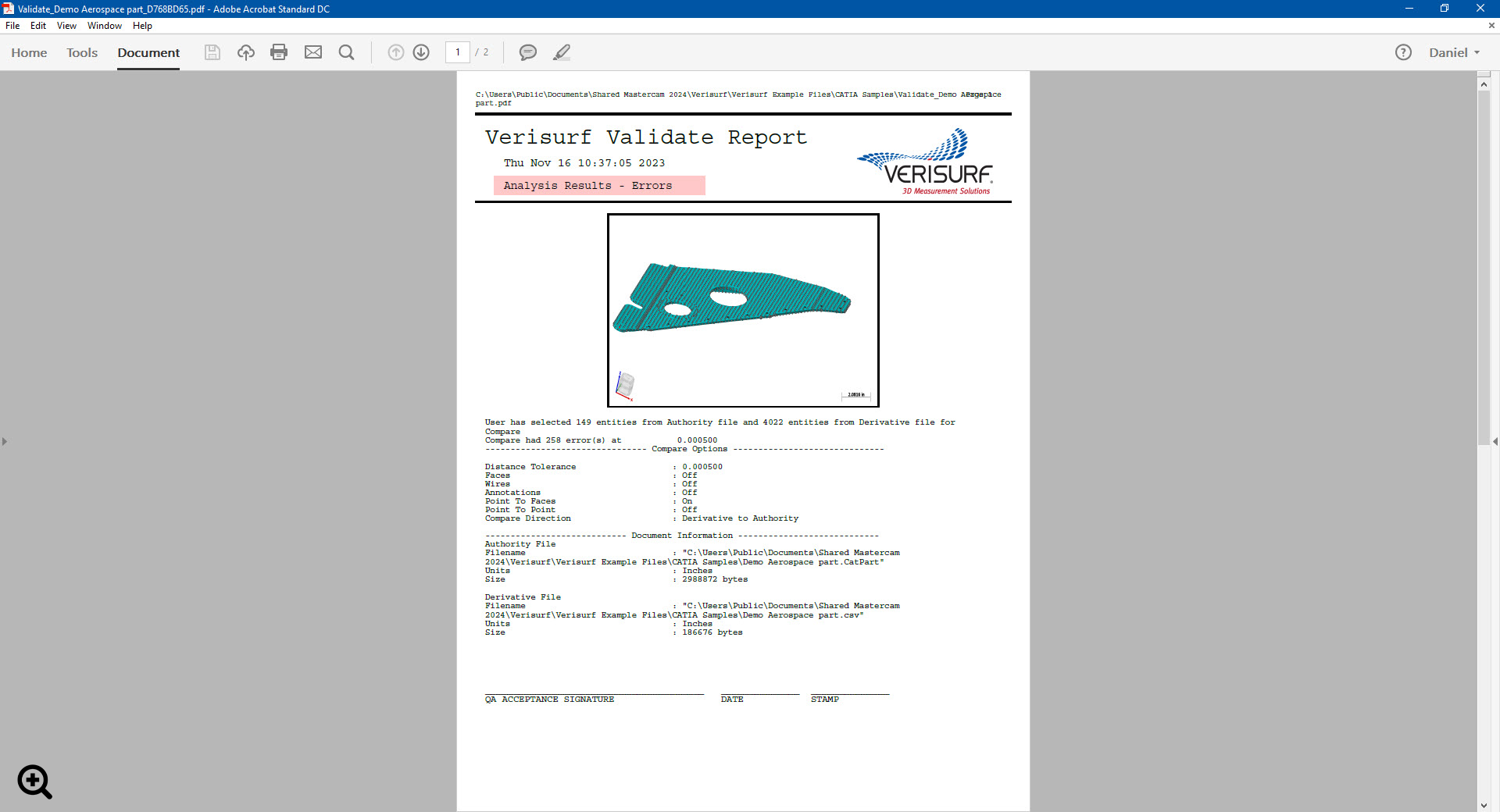
1.7. VALIDATE report with file and analysis details and optional signature block
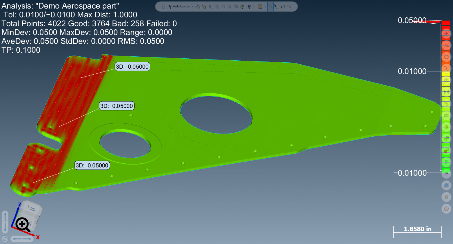
2. Analyzing VALIDATE Results=”Fail”:
2.1. VALIDATE generates “Fail” result, report provides a summary
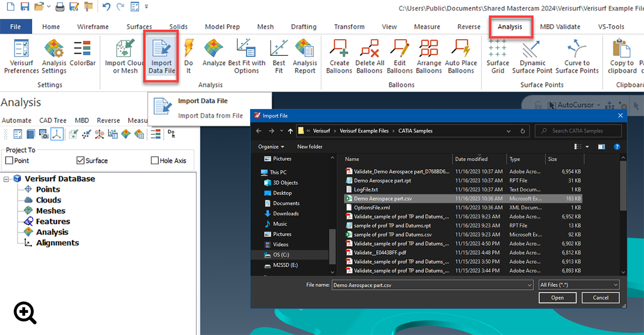
2.2. VALIDATE automatically saves a .csv file of the validation pointcloud in the same folder as the source/authority model; for analysis of failed regions, import file into Verisurf ANALYSIS*
* Requires Verisurf ANALYSIS module license
2.3. Select “Analyze” to project the VALIDATE dataset pointcloud to the imported model and display errors between authority vs. derivative models
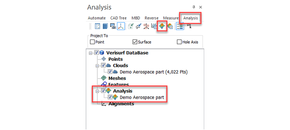
2.4. Use ANALYSIS settings to refine the display of the results as required to highlight FAILED areas of the translated model
Verisurf-Embedded VALIDATE Workflow
Kubotek Kosmos VALIDATE – External Stand-Alone App
Featuring

VALIDATE
Verisurf VALIDATE’s original integrated software module performs validation on a CAD model after importing it into Verisurf using embedded Kubotek Kosmos functionality. Subsequently, Verisurf VALIDATE now includes the Kubotek Kosmos VALIDATE external, stand-alone application in addition to the integrated version.
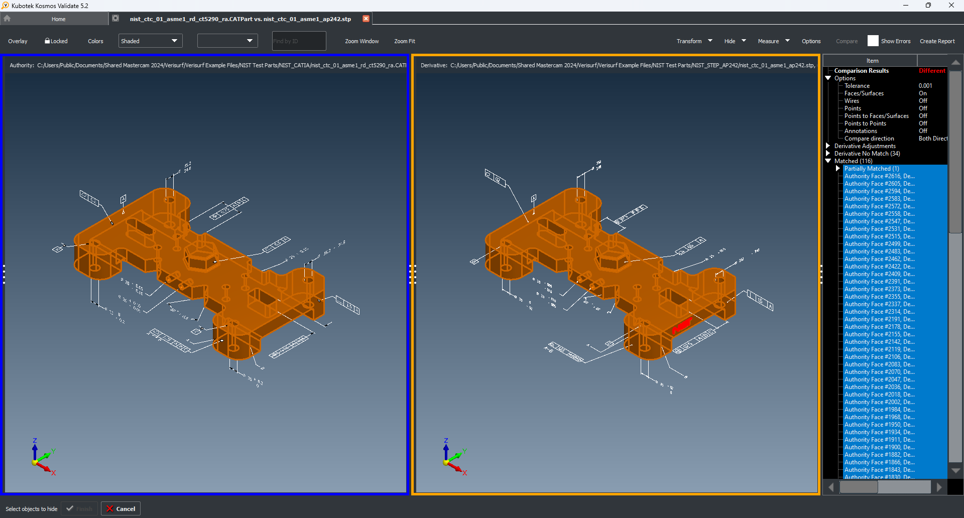
With Kubotek Kosmos VALIDATE stand-alone, users import the “authority” or source CAD model into the application. In the stand-alone app, a “derivative” model in neutral file format such as IGES or STEP is also imported for comparison against the authority model. Kubotek Kosmos VALIDATE provides numerous comparison, analysis, display, and reporting features to comply with DPD. It also includes additional capabilities for configuration control among other benefits.
Advanced Geometric Comparison identifies, highlights and documents missing or inaccurate model geometry that would be hard or impossible to find with visual inspection.
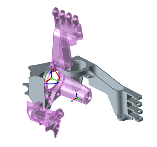
Geometry Orientation Validation identifies, highlights and documents differences in geometry orientation which often results from moving or rotating a part in an assembly or changes in part coordinate systems.
MBD Annotation Validation checks for differences in semantic GD&T that may occur during translation including small deviations in feature control frames which are very difficult to visually identify in complex parts. In this case the STEP AP242 model annotations matched but the NIST characters highlighted in red failed translation validation.
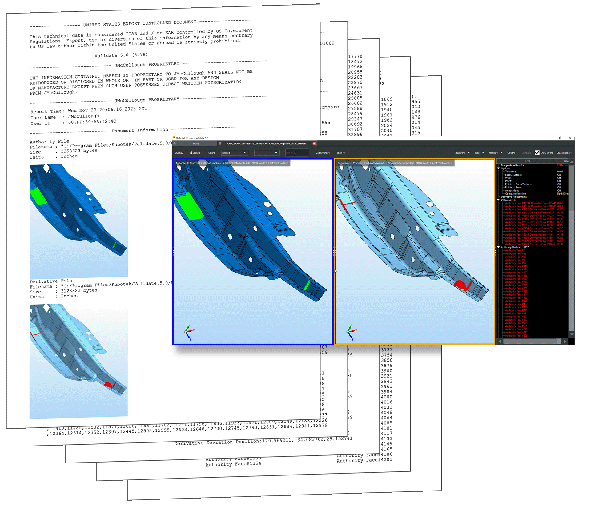
Validation Reports are an important part of the documentation process. In this case the differences between the Authority File and Derivative File are clearly listed in the software dialog, highlighted in the software graphics display and reported in a multipage sharable PDF file.
Kubotek Kosmos VALIDATE Workflow
Product Acceptance Software (PAS)
Product Acceptance Software (PAS) Requirements are Imposed by Boeing Standard D6-51991 Rev N Section 3
What is Product Acceptance Software (PAS)?
Product Acceptance Software, also known as PAS, is software used in various industries, particularly in quality assurance, product development, and project management. Its primary purpose is facilitating and automating accepting or approving a product, system, or project. Here are some of the essential purposes and uses of Product Acceptance Software:
- Quality Assurance: PAS helps ensure that a product or project meets predefined quality standards, specifications, and requirements before release to customers or stakeholders. It aids in identifying and resolving defects, errors, and issues to improve the overall quality.
- Project Management: In project management, PAS verifies that project deliverables align with the project requirements and objectives. It streamlines the acceptance phase, making it easier for stakeholders to provide their approval.
- Compliance and Regulatory Requirements: For industries with strict regulatory requirements (such as healthcare, finance, and aerospace), PAS can assist in verifying compliance with specific standards and regulations. It helps organizations demonstrate that their products or systems meet legal and industry-specific requirements.
- Testing and Validation: PAS often integrates with testing and validation processes to confirm that the product or system functions as intended and passes all required tests and checks.
- Collaboration: PAS streamlines communication and decision-making among stakeholders, such as project managers, developers, testers, and end-users. It provides a centralized platform for sharing information and feedback.
- Documentation: PAS helps document the acceptance process, including the criteria used for acceptance, who approved it, and when accepted. This documentation is for audit purposes and to establish a clear history of product acceptance.
- Workflow Automation: PAS can automate acceptance workflows, ensuring that the acceptance process follows a predefined sequence and that all necessary parties are involved in the decision-making process.
- Traceability: It enables traceability by linking product requirements to acceptance criteria and test cases, making it easier to track and verify that each requirement is met.
Product Acceptance Software plays a crucial role in streamlining the acceptance and approval of products, systems, or projects, enhancing quality control, compliance, and collaboration throughout the process. It helps organizations ensure that their products meet the expectations and requirements of stakeholders and relevant standards.
Product Acceptance Software (PAS) per Section 3. Boeing QUALITY ASSURANCE STANDARD FOR DIGITAL PRODUCT DEFINITION AT BOEING SUPPLIERS document number D6-51991 Revision N
3. Product Acceptance Software (PAS)ref. a
3.1. Commercial Off The Shelf Software – The supplier shall document and maintain documented processes for the control of Product Acceptance Software (PAS). PAS
includes software used in the acceptance of special tooling and products.
3.1.1. Supplier must document and maintain PAS procedures and reference applicable documents in their documented DPD processes. Documented results shall provide for identification of software name, software version and validation results when used for QA applications.
3.1.2. Procedures or processes will be maintained to prevent unauthorized changes, to limit personnel access to software files, and to archive masters and duplicates.
3.1.3. Supplier should request objective evidence or certification/accreditation (independent) of the PAS from the software manufacture per ASME B89.4.10 or equivalent. The supplier shall maintain documentation for certification/accreditation as a means of identifying approved PAS, version control and QA management approval. Sample testing of existing product and tool programs following new or revised PAS installation to verify compatibility is considered a best practice.
3.1.4. In the event supplier is unable to obtain objective evidence or certification of the PAS from the software manufacturer, supplier is responsible for verifying PAS prior to product acceptance use. Examples of PAS functionality verification include using calibrated standards, known physical artifacts or embedded software to test feature construction and output accuracy. Examples also should include GD&T functions, temperature compensation, CAD translations and software that controls hardware.
3.2. Computer Aided Manufacturing Software – When used for inspection (i.e. CNC On-machine probing, etc.) the supplier shall develop and maintain documented processes for configuration identification and control of CAM software and must meet the requirements of sections 3.1.1 through 3.1.4.
3.2.1. Supplier must verify numerically controlled software prior to product acceptance and maintain records.
How does Verisurf Perform Product Acceptance Software (PAS) testing?
Verisurf helps manufacturers address Section 3.1.3 and 3.1.4 Product Acceptance Software (PAS) requirements of the Boeing D6-51991 Rev N standard. Verisurf provides objective evidence of independent PAS certification, including PTB Certification. Verisurf also includes a dataset provided by an independent source (NIST), which has been embedded into Verisurf and is used to test and validate feature construction and output accuracy.
NOTE: Verisurf is a PAS and is considered a commercial off-the-shelf software used to accept tooling and parts.
- Embedded NIST Test Tech-Tip
- The NIST test contains a total of 240 datasets representing the following feature types per ASME B89.4.10-2000 standard, Methods for Performance Evaluation of Coordinate Measuring System Software. Below is a quick summary of the requirements per feature evaluated per the Instructions for using the NIST Reference Pairs
-
- LINES: X, Y, Z, I, J, K
- PLANES: X, Y, Z, I, J, K
- CIRCLES 2D: X, Y, Z, I, J, K, DIAMETER
- CIRCLES 3D: X, Y, Z, I, J, K, DIAMETER
- SPHERE: X, Y, Z, DIAMETER
- CYLINDER: X, Y, Z, I, J, K, DIAMETER
- CONES: X, Y, Z, I, J, K, DISTANCE, ANGLE
NOTE: GD&T controls such as form, orientation, and location are a result of the feature construction from each dataset and therefore not included in the NIST Reference Pairs.
- Independent Certification/Accreditation
- Objective evidence or certification/accreditation (independent) of the PAS from the software developer per ASME B894.10 or equivalent.
- Equivalent: Physikalisch-Technische Bundesanstalt (PTB), an internationally recognized Metrology Institute based in Germany, conducts algorithm testing using the Gaussian theory method of least squares to assess Verisurf’s ability to accurately measure and construct lines, planes, circles, spheres, cylinders, and cones. PTB Certification Verisurf 2021
NOTE: All deviations of the algorithms under test were below the maximum permissible errors (MPE) for all quality characteristics. Characteristic variable Unit MPE Orientation µrad 0.10 Location µm 0.10 Size µm 0.10 Angle µrad 0.10.
PAS Testing and Compliance by Verisurf Customers
The PAS Inspection Artifact
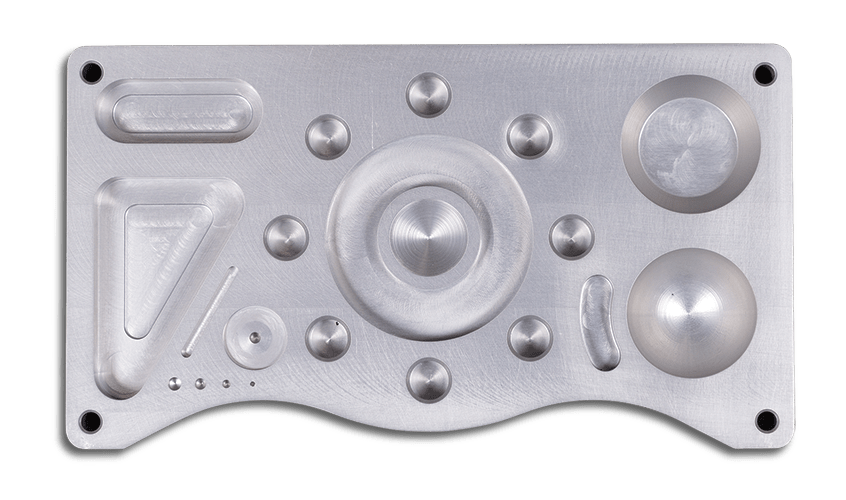
Verisurf’s training and demonstration precision machined part, with contoured profiles and primitive features such as holes and slots, makes an excellent artifact for PAS compliance.
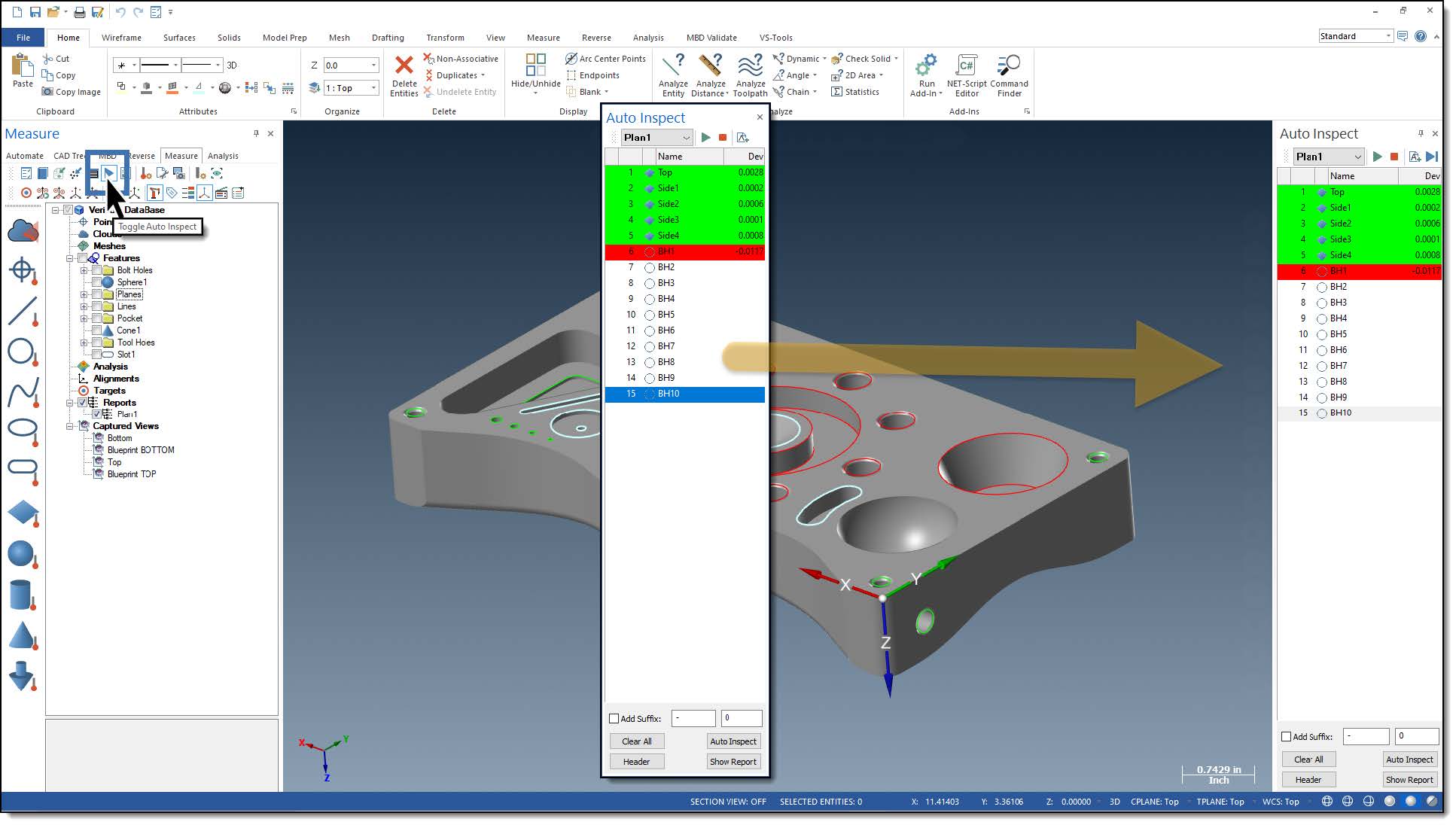
The PAS artifact is certified with a Verisurf AUTOMATE inspection plan, then saved and controlled as a baseline. When changes are made in the PAS or related systems, the AUTOMATE plan is executed to ensure that the PAS output remains within tolerance of the baseline inspection results.
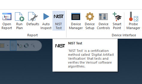
Verisurf Built-In NIST Test
The Verisurf NIST Test is in the MEASURE ribbon bar under Report controls. Use the NIST Test to execute a digital artifact verification process that tests and verifies Verisurf software’s algorithms.
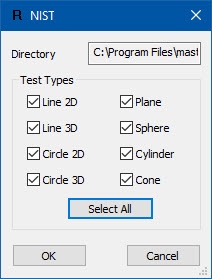
The United States of America’s National Institute of Standards and Technology (NIST) provides the algorithms. The current standard for testing is lines (2D and 3D), circles (2D and 3D), cylinders, cones, and spheres is ASME B89.4.10-2000 of methods for performance evaluation of coordinate measuring system software.
NIST has provided a dataset to Verisurf software. This dataset simulates measurements from a CMM and contains form and measurement errors per the ASME standard listed above. When the NIST Test button is selected, the selected dataset is loaded, a fit is executed, and compared to the NIST standard. A report is generated in the data tree.
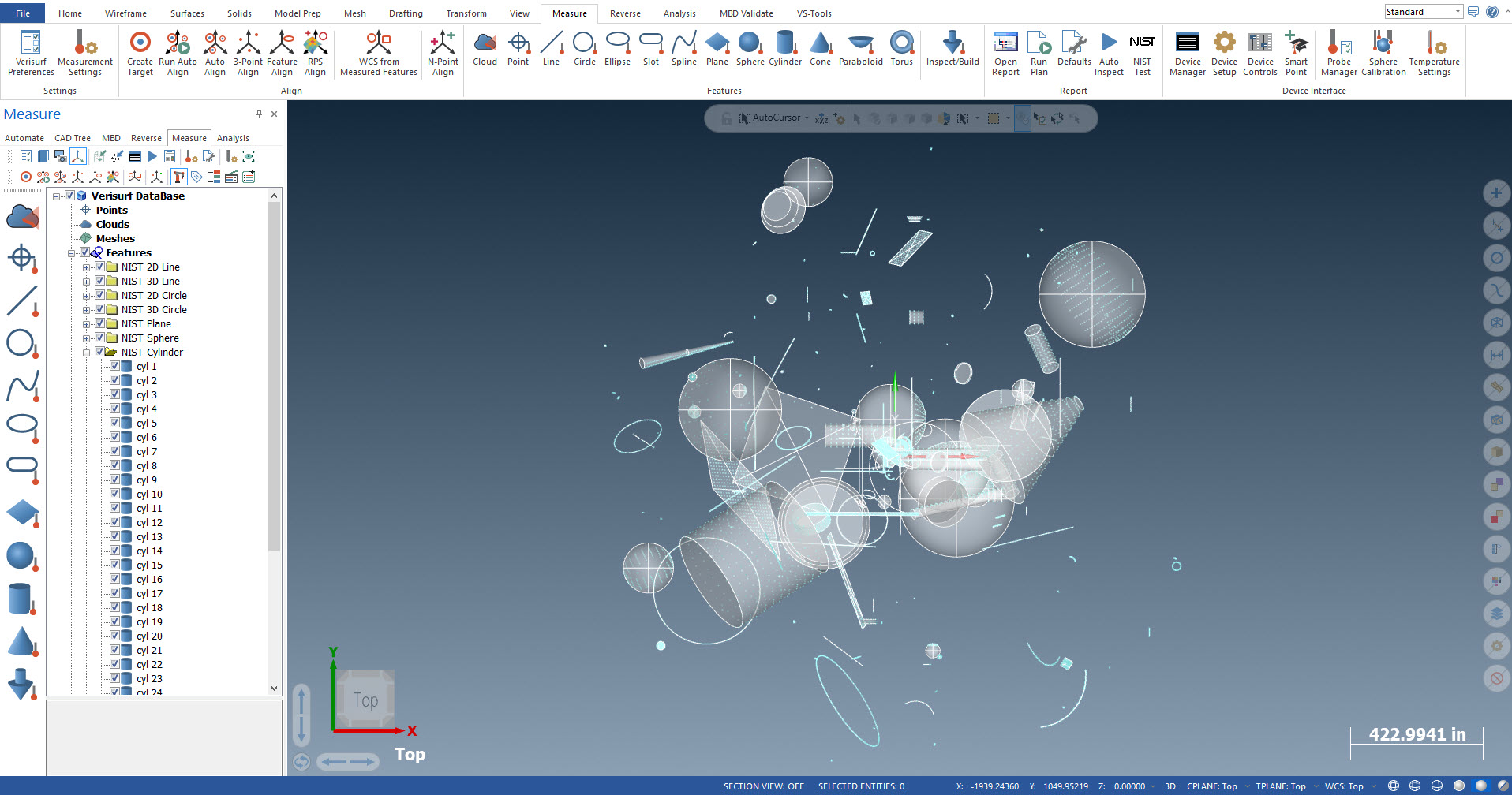
NIST Test results in Verisurf software
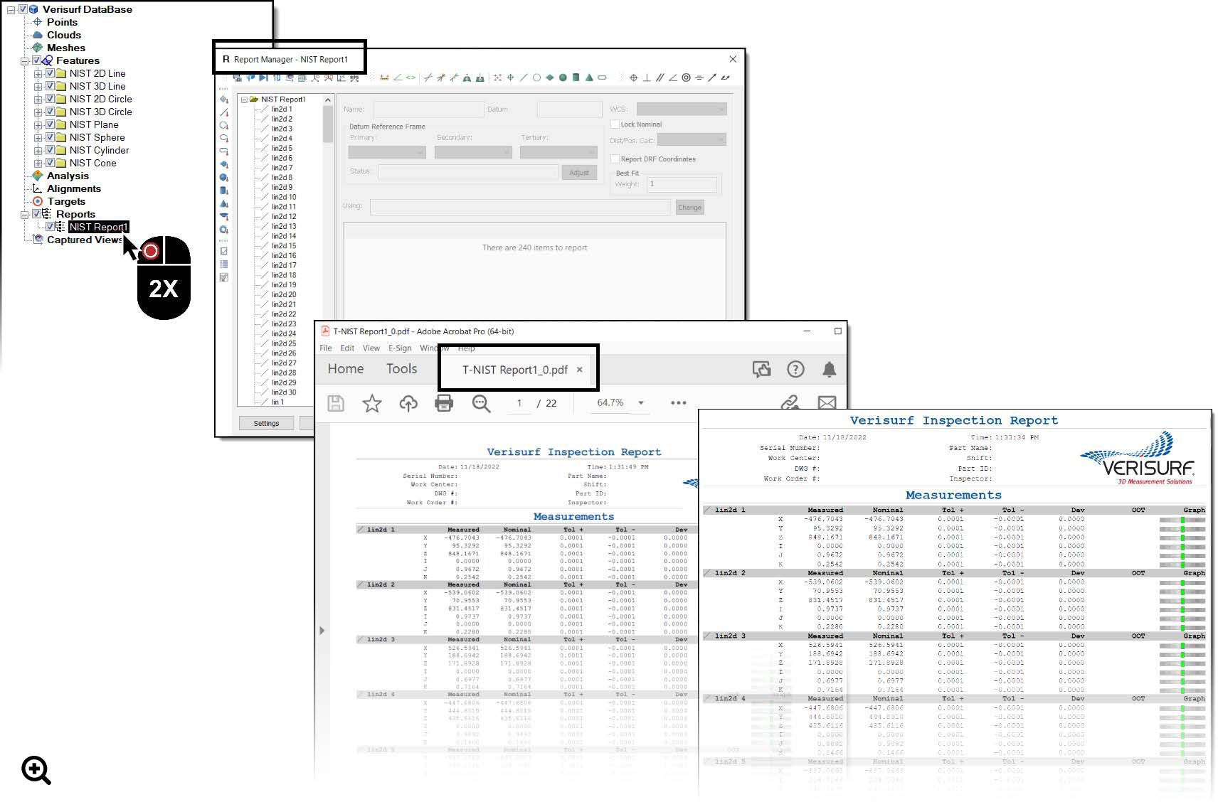
NIST Test Report
The NIST test results can be printed or saved to the computer hard drive, network, or external storage device. Using the Report Manager, you can generate; PDF, HTML, Excel, Word, PowerPoint, Text, or Database reports of the NIST Test results.
The NIST website on algorithm testing: https://www.nist.gov/pml/engineering-physics-division/dimensional-metrology/algorithm-testing
Author: Scott Knoche – Verisurf Software, Inc. (technical marketing & sales at Verisurf since 2002)