

What is a CMM?
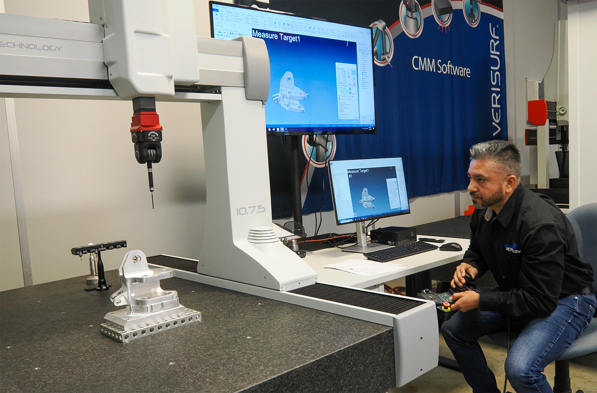
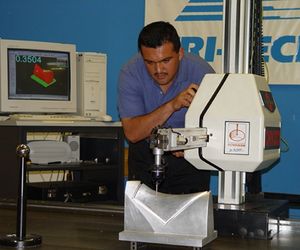
The CMM (coordinate measuring machine) is a measurement system designed for precise verification and documentation of manufactured parts and assemblies. It is programmed and/or controlled to take measurements of size, form, dimensions, and relationships between features. Verification is based on a comparison between the part and the design definition established by engineering drawings and/or CAD. The manufactured part is checked against its design to ensure it fits well with the next assembly and performs its intended function as part of that assembly. Beyond verifying dimensions – checking to see that features are parallel, concentric, flat, or at the correct angle relative to other features can be of great consequence. Some of these measurement needs can be very challenging and time-consuming. CMMs help to overcome these challenges.
Main components of a CMM:
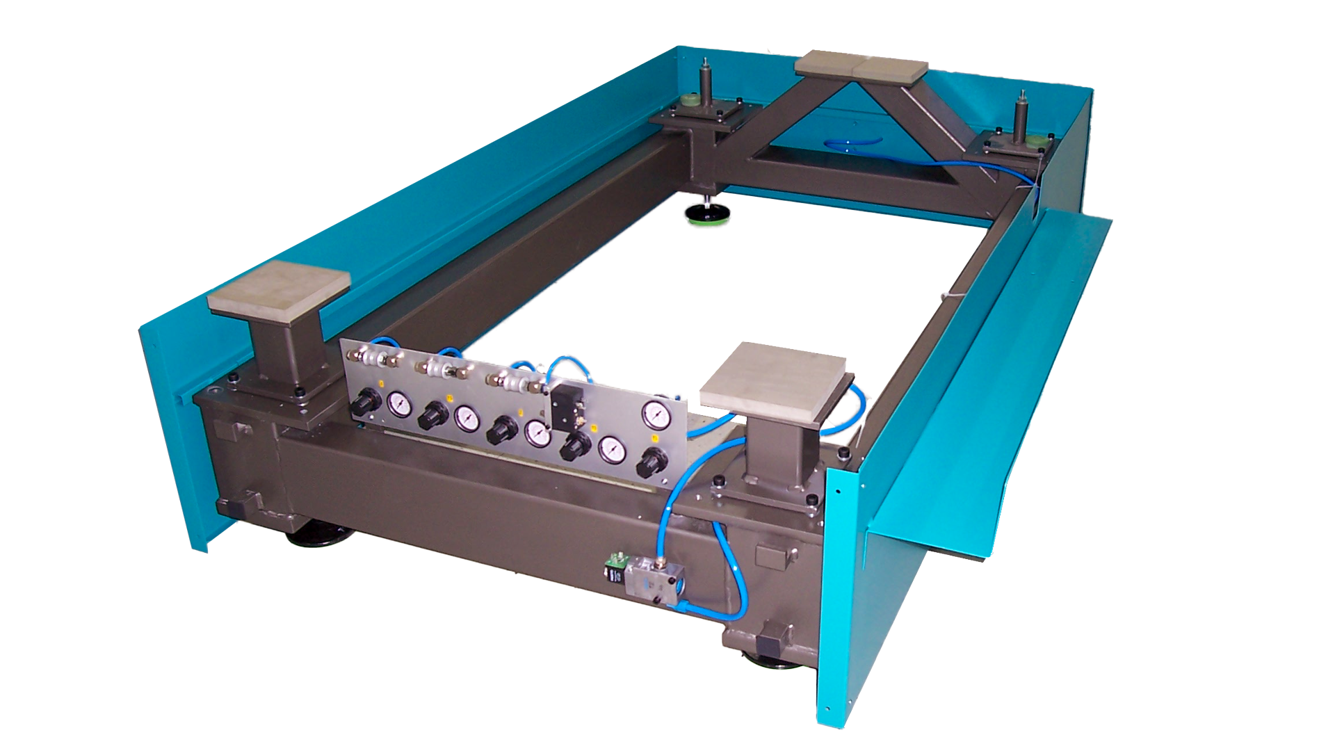
- Base frame structure and measurement table (or “surface plate”) – The table is usually granite stone, thick, flat, and stable. Large machines may have a base built into the floor. One or two guideways may be built into the table for the upright structure.
- Upright, translating (sliding) structures – Vertical and horizontal beams with guideways that are moved by servo motors and are fitted with precision measurement “scales” that track them. These assemblies usually support the “X, Y & Z” movement of the machine, so each may be referred to as one of the “axes” of the three.
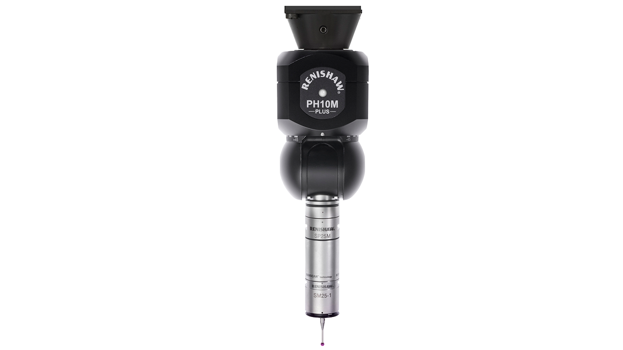
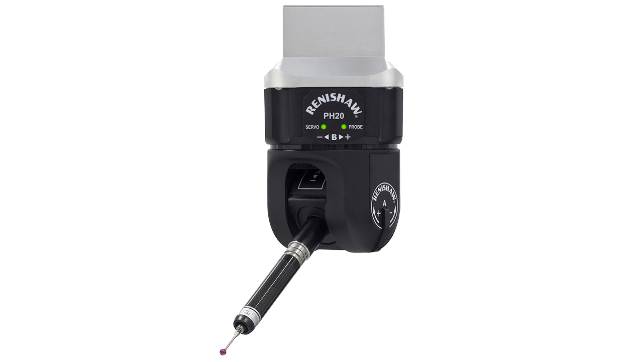
- Probe head assembly – The working end of the machine that takes measurements is typically, but not always, an articulating “touch-trigger” design. The probe head assembly and the probe assembly are suspended from the X,Y,Z structure and can have either a manual or motorized 5th axis articulation for probe angles.
- Qualification/calibration sphere.
- Machine controller.
- Probe controller.
- Joystick controller – For manual movement of the machine and probe head.
- Computer workstation.
The inspection article is fixed firmly to the table so that it does not move or deflect while being probed. It is held by clamp-type fixtures or other means. The touch-trigger or other probe type is suspended from the head with adapters and a shaft threaded to a ball known as the “stylus.” The probe assembly has an integrated sensor that communicates the stylus touches and the position of the tip. This data is streamed back to the probe and machine controllers. The whole system talks to the software incorporated into the computer workstation. The machine is programmed by the CMM software, and acquired data is mathematically fit, organized, compared, and reported by the software as well.
Detailed Breakdown of Major Components of a CMM
Purpose in Common for All Types of CMMs
- Inspect manufactured part(s) to ensure compliance with design and contract requirements
- Create a reliable record of the as-manufactured part including dimensional and relational aspects of its geometry
- Compliance with requirements for first article inspection reporting (FAIR)
- Perform in-process checks
- Achieve scrap reduction or elimination
- Compliance with ISO or other industry-specific standards
There are varied approaches towards achieving the measurement goals to be realized with a CMM. A lot depends on the use-case, accepted technical association’s rules and standards, accuracy, and repeatability needs. Three-dimensional contoured shapes cannot be verified by hand tools such as micrometers, calipers. and gage pins. Not even height gages or other 2-dimensional measurement tools will do the job. Many relationship measurements such as GD&T callouts such as parallelism, concentricity, etc., require considerable time to set up and measure with dial indicators or “old school” techniques. Calipers and micrometers touch the feature being measured in only two points of contact. Measurements vary due to the inspector’s grip on the gage and workpiece, with readings varying from one inspector to the next.
Measurements must be written down and therefore slow the process and are subject to transposition errors. So, in many cases, CMMs are the answer. When evaluating which type of CMM design and features are best for your needs, you should always test some of your parts to your specifications on the various types of CMMs being considered, and weigh the pros and cons.
CMM Design Basics Overview
The coordinate measuring machine (CMM) has been around for decades, and it has come a long way in its evolution. For these measurement systems, competition amongst the OEMs is part of what has taken the technology to new heights. Also, third-party software developers, service providers, dealers, customers, and competing technologies drive improvements in CMM capabilities and efficiencies as well. The main purpose of the CMM is precise dimensional shape and size measurement, which includes the position and orientations of features on the part and the relationships between features.
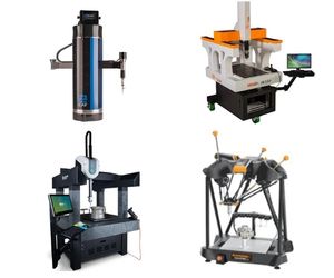
CMMs come in all sizes to suit the size of parts and accuracy needed for them. Also, budget and other practicalities are considerations. There are a small number of machine types that have evolved and are prevalent in the market. This article intends to present an overall look at the basic characteristics of their structural layouts. This might be helpful towards understanding which style suits your needs best when looking for a system.
CMM Structural Designs
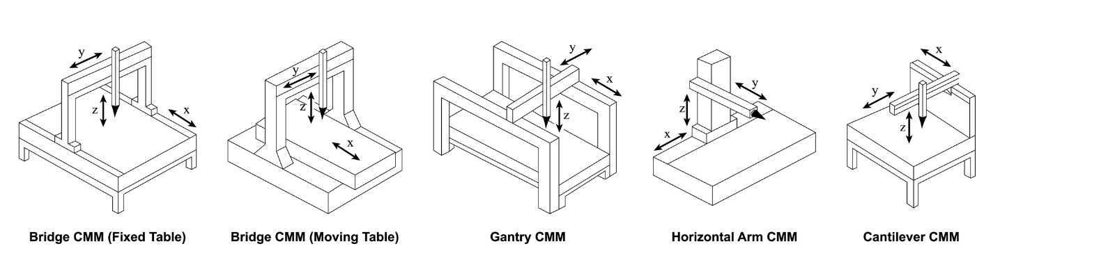
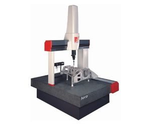
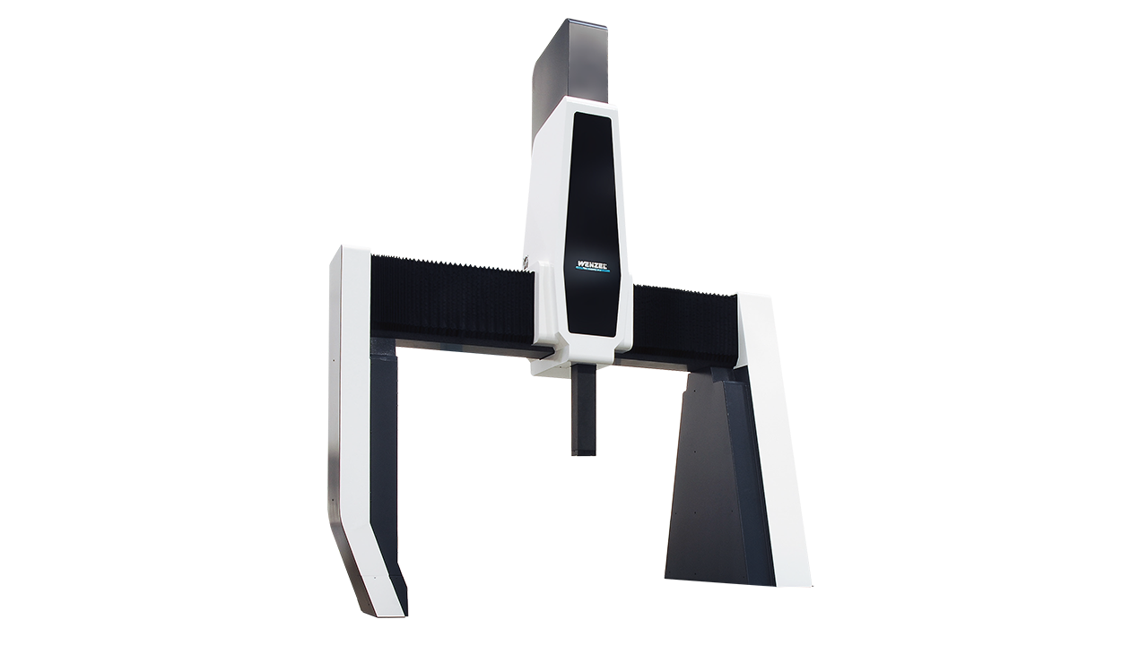
BRIDGE
This is the most common style. Its key design feature from which it gets its name is an upright “carriage” structure consisting of two vertical beams that support a horizontal (bridge) beam connecting the two vertical elements. The bridge moves back and forth transiting the table, moved by an electric servo motor, and its position is tracked by precision measuring scales. The scales consist of a fixed, coded tape that is interpreted by reader heads that are affixed to the moving structural element. Older systems communicated via an analog system that read position via an electronic signal, interpreted by a decoder, followed by transmission of the position signal to the machine controller. Analog systems have been supplanted by digital scales that communicate via hexadecimal data stream communication (although there are still analog systems in use). Digital scales are now the standard.
Suspended from the bridge beam is a vertical moving beam (Z-axis) that is also motorized, and position read by a scale of its own. It has a moving main structural element that carries the probe head and probe. The bridge design is optimized for accuracy, at a slight loss of access to the measurement table (meaning diminished access to the inspection article). Due to its accuracy and prolific acceptance and distribution, bridge CMMs come in many sizes. They are offered in sizes from smallish, maxing out at microwave oven-sized parts, to largeish, maxing out at the size of a Smart Car.
 |
Pros – Accuracy. Availability. Moderate cost. Widespread use and therefore access to service, expertise/consulting, and parts.
Cons – More obstruction of access to inspection article envelope than cantilever or horizontal arm types. |
CANTILEVER
This design has a structure that unlike the bridge-type CMM with two moving, vertical beams supporting the crossbeam, is supported by a guideway only on one side. It is therefore cantilevered out from that side as the only supporting leg. The side support has a guideway at the top along which the crossbeam moves (in the X direction, for example). The vertical probe support beam transits the crossbeam (Y direction) and has the mechanism that moves the up/down Z strut that carries the probe head. This design gives better access to the inspection table but suffers some loss of accuracy. Since the droop effect would multiply as it extends further from the Z beam, the cantilever design is better for smaller parts and when access takes precedence over accuracy.
 |
Pros – Easy access through 3 out of the 4 sides to the inspection table. Better for automation and part change-out. Less expensive. Suited to smaller parts.
Cons – A degree of reduced accuracy. Less common these days so support, parts, repair may be issues. |
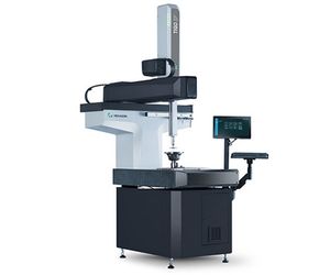
HORIZONTAL ARM
This layout was more popular in the past but is still marketed for specific needs today. It is a lower-cost solution, but allows open access to the table, albeit a little less so than the cantilever design. This machine has been very popular for automobile design and shape development, especially for clay modeling and sculpting. It has been prolific for whole-car body panel measurement where the attach points and relationship between panels are of concern. On a side note, non-contact scanners have all but taken over the job of body panel and stamped part contour analysis. Scanning has become the relied upon technology for compliance with Class-A, customer-facing smoothness and continuity. This is also true for reverse engineering, as-built, and tool development of stampings or non-metallic “body-in-white” for automobiles.
A common variation of the horizontal arm setup is pairing two towers with probing heads, like two CMMs in one. In this configuration, both sides of a car can be reached easily in one setup. Versions of horizontal arm CMM were a low cost, sufficiently accurate, granite table-based design. The auto body type versions are usually mounted to the floor instead of on a granite table, giving them a large measurement range.
 |
Pros – Inexpensive and open access. Historically chosen for auto body digitizing and inspection.
Cons – Getting harder to find parts for older table-based versions. Less accurate. Non-contact laser or white light scanning technologies have supplanted some of this machine design’s main market. |
GANTRY
This is often thought of as a CMM for larger parts. But there are smaller versions as well. For the big ones, there are two large steel fabrications erected as the machine’s side structures. The crossbeam runs on top-mounted guideways down the length of those structures. With the Z-axis beam suspended from the cross member, it can transit the crossbeam while moving up and down to carry out the Z movement. Big gantries are mounted to the floor typically, and smaller ones have the usual granite surface plate.
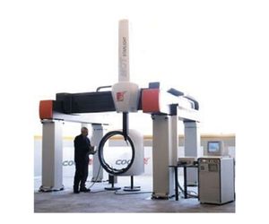 |
Pros – Appropriate and accurate for large parts as the machine has lots of daylight between the probe and floor and other structures. Stable, rigid design for larger formats. This design has often been chosen as preferred for the shop environment.
Cons – The least access to the table and inspection area where the inspection article is clamped. The large gantries are cost-prohibitive unless needed for tight tolerance, large parts. Laser trackers have become a mainstay for portable CMM inspection of large parts and tooling. Therefore, they have supplanted large gantry machines in many cases. |
VARIATION – MOBILE & SHOP-FLOOR CMMs
The most common CMM installation requires a climate controlled CMM room or metrology lab that houses one or more CMMs isolated from the shop environment. This controlled setup reduces inconsistencies and unknowns of an unstable environment. Temperature variations and thermal expansion are big concerns in metrology. However, there are several benefits of having the CMM close to the work such as in a work cell. One option might be to incorporate the CMM with automation. If a robot or other system is added, a lights-out operation is possible.
Not necessarily new but becoming more common are shop-floor CMMs. A shop floor CMM might even be operated by the same person who made the part. These machines eliminate commonly used air bearings, environmentally controlled rooms, and high voltage requirements of typical CMMs. They bring the machine to the work. They accommodate temperature variations in the shop via designed-in compensation hardware and software features.
 |
Pros – Parts are dispatched quicker, less waiting for processing through the CMM lab. The closer the discovered problems are to the problem source, the quicker and easier they are resolved. Better ownership of defects by the part makers, and fewer disputes between manufacturing and QA. Parts are measured in the same environment in which they were made, possibly eliminating uncertainty of thermal expansion. Reports Metrology News publication,“Inspecting 3D features during the manufacturing process minimizes reaction time for machining adjustments.”
Cons – The trained CMM experts may not be as accessible as they are in a CMM lab, so personnel issues may arise. Not everyone is convinced that the manufacturing environment is suitable for CMM inspection. Even though the machines are made for the shop environment, they are still exposed to environmental and shop impurities that can cause harm to them. Control, maintenance, assurance of machine accuracy, and calibration status may be more difficult to sustain. |
In Summary
There is a lot to consider when deciding on a CMM type to fit the needs of your enterprise. Much depends on the use-case, accepted technical association’s rules and standards, typical part size, accuracy, and repeatability requirements. Another consideration is the support and expertise that exists in your region. This is not an aspect that should be disregarded. When beginning use of CMM technology for the first time, and even for your needs that you expect down the road, you will find that good technical support and consulting assistance are crucial to success.
For a closer look at Verisurf’s CMM programming, reporting and additional related options click here.
If you are already working with or considering one of the excellent CMM OEMs in the industry, we encourage you to ask them for Verisurf as your software choice. If you already have a CMM and would like to consider upgrading, click here for more info.
Major Components of a CMM
Granite Measurement Table
Ensures robust rigidity, flatness, squareness, and stability necessary to maintain size and shape during measurement. It also helps maintain durability over time and varying conditions.
Base Structure
Provides a reliable foundation for the heavy granite table. It is a strong, rigid steel weldment that in conjunction with the table provides stability, leveling and anti-warp features, plus squareness control. It can include simple, passive vibration control elements or they may be more sophisticated as required. The base can be used to affix and route plumbing for the machine’s pneumatics and wiring for electrical distribution.
.
Probe Head Assembly
The probe assembly is the technology-packed, precision, electro-mechanical unit to which the typical touch-trigger probe is mounted and by which it is positioned. It provides motorized articulation to the various angles directed by the inspection program, and manages the high-tech sensors that precisely acquire data for probe position and touch-trigger events that stream data to the control system.
Alternative Probe Systems
Early CMMs had the touch-trigger probe fixed in a straight down attitude. Later models advanced to variable angle, manually indexable designs. Ultimately technology moved to where it is today, to motorized heads that index automatically. All of the articulating-index varieties are still built today and are considered “3-axis” systems.
5-Axis and Tactile Scanning Probe Systems
The articulating probe along with advancement in sensors ultimately evolved into “5-axis” probing systems. Five-axis probing is characterized by “head-touches,” in which is the probe actually captures touch-trigger points as it articulates into contact with the surface of the inspection article. With the addition of motorized rotation about the Z axis, the 5th axis came into play.
Also advancing the state-of-the art is tactile scanning. This involves placing the probe in contact with the inspection article and dragging it along the part surface while recording a stream of data as it scans. Combination of 5-axis and tactile scanning became the most advanced adaptation of tactile CMM probing.
Controllers
Machine Controller
The controller provides the digital-electronic interface with the CMM’s three drive motors that provide movement of the X, Y, and Z moving structural elements of the machine. It also communicates with the linear scales and reader heads that provide positional feedback to the system. Critical calibration and compensation of the CMM is accomplished within the machine controller. It communicates with the system software on the CMM’s personal computer workstation to interface with the probe management module and software path programming application.
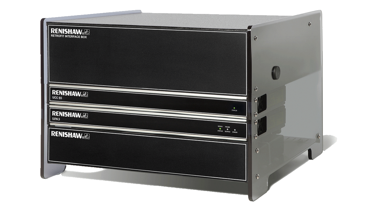
Probe Controller
This electronic system communicates with the head and touch-trigger probe in conjunction with the machine control and control application software. It drives the 2 motors and reads the 2 encoders that communicate the probe rotation and angle, plus output from the touch trigger events of the probe itself.
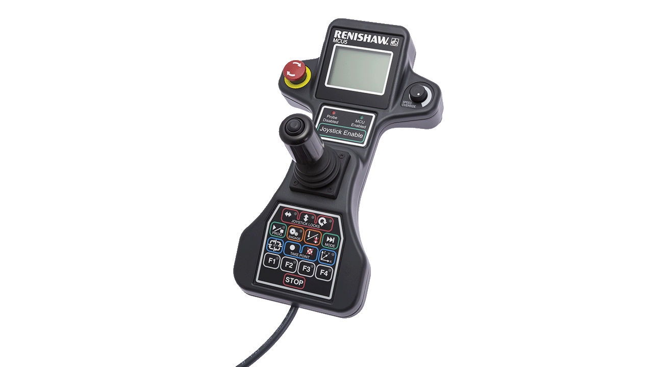
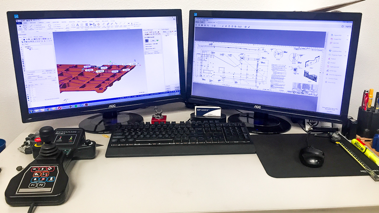
Joystick Controller/Jogbox/Hand Controller
The joystick provides manual control of the CMM for a variety of purposes, primarily manual measuring or performing a preliminary manual alignment before commencing an automated probing program. The jogbox lets the user manually move the carriage up/down and translate (X, Y, and Z) and to take “probe hits,” moving the probe to contact the inspection article and take measurements. It has buttons to execute/start/stop programs, control the speed of movement, and includes a safety “dead man” button to prevent unintentional operation.
Carriage
This assembly of upright, translating (sliding) structure provides stable movement of the probe system across the table while suspended from the structure. The quill translates up and down along the Z axis, the bridge or arm allows the quill and head to translate side-to-side along the Y axis, and the bridge or arm travels along the length of the table on a guideway for the X axis. (may vary between machine manufacturers and models).
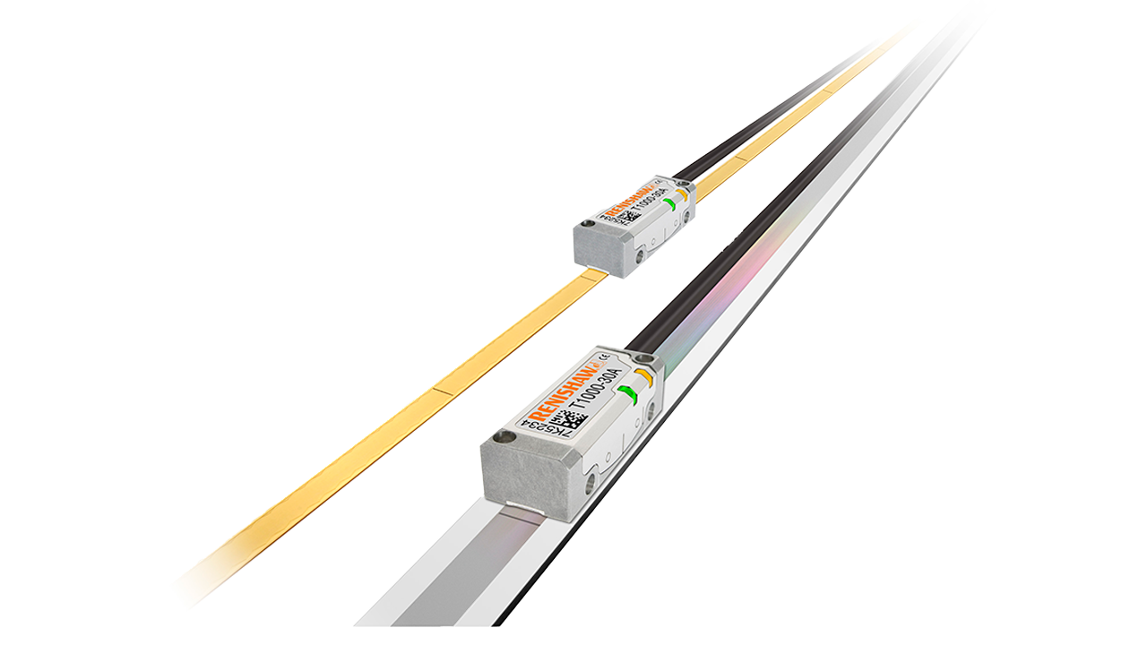
Precision Scales and Reader Heads
Modern versions use digital technology comprised of a linear tape scale fixed to the relevant structural element (of the X, Y, or Z axis components) and a reader head an adjacent structural piece that moves over it. This provides a very accurate position sensing and signal output that is sent to the control system for movement control and data recording.
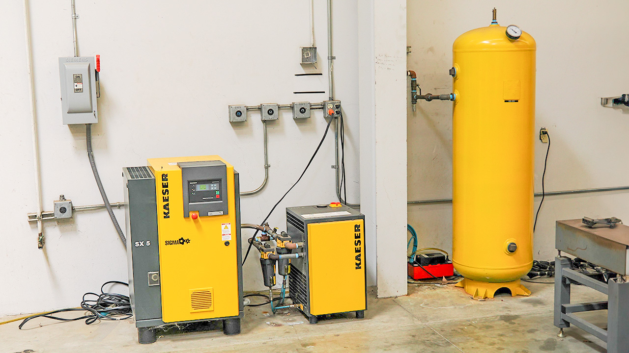
Conditioned Compressed Air System
To meet the requirements of precision air bearings common to most CMMs, conditioning of the compressed air supply is crucial. The system includes compressor, filter, dryer, pressure tank/reservoir, and controls. Maintenance and monitoring of the system is required for the CMM to work and to last. Improper or insufficient air supply can cause significant damage to the CMM.
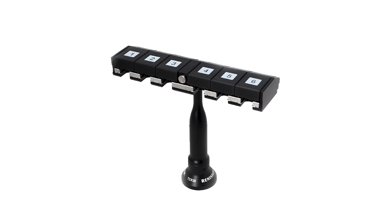
Probe Automatic Quick Change Rack
A nice option for CMMs is an automatic probe change rack. It allows faster CMM program cycles by automating all of the necessary probe changes to perform part inspections without halting the machine to do changes, thus speeding and streamlining the process. It allows the program to run unattended but more importantly, shortens the cycle time.
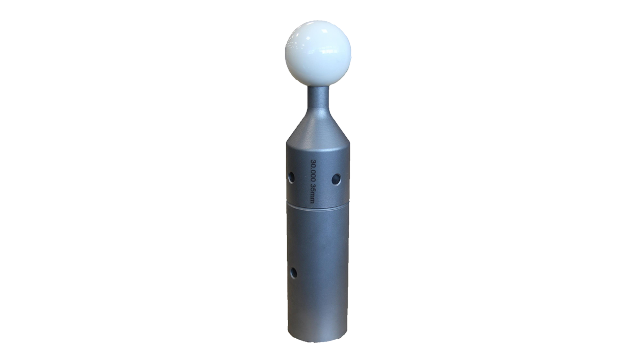
Qualification/Datum/Reference Sphere
A high precision sphere, typically made from durable, hard ceramic, is firmly mounted to the CMM table to provide a known artifact for probe qualification and calibration, as well as for accurately setting the machine “zero” or origin of its reference system. For indexed probe systems, it is relied upon for individual calibration of all probe angles that are part of the inspection program. More modern systems rely on an accurate zeroing with “inferred” calibration that interpolates throughout the probe’s range of angular movement.
Computer Workstation
While CMMs are sophisticated and highly precision, productive inspection systems, the software that “programs” and operates them does much of the work of the inspection. Modern software does not require complex programming code or even legacy text sequencing. For the most part they are programmed via an intuitive, graphical user interface that uses CAD models as the nominal baseline for inspection. A modern computer workstation with up-to-date operating system, essential hardware components, and programming software is key to productivity and longevity of the system.
Part Holding/Adaptive Fixturing
Due to the endless inspection article shapes, sizes and features that may be encountered, modular fixturing is often employed to hold parts firmly and securely in place for inspection. This is essential in order to get accurate measurements. Some parts require special fixturing be made specifically for the task, both for access and stability of measuring. Good fixturing can also speed up the process of the inspection by reducing the number of steps or probe changes to do the job.

Author: Scott Knoche – Verisurf Software, Inc. (technical marketing & sales at Verisurf since 2002)