
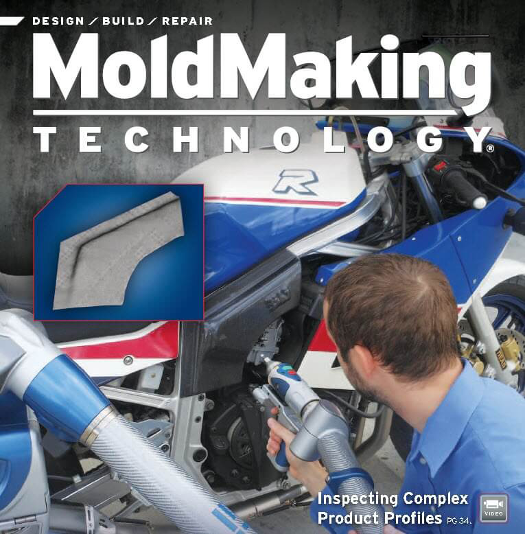
Inspecting Complex Product Profiles
Using metrology software and a portable CMM, mold manufacturers can efficiently handle exceedingly complex surface profile requirements
Read this story in Moldmaking Technology Magazine HERE
Get a PDF version of this story HERE
By David Olson, Director of Sales & Marketing for Verisurf Software, Inc.
Inspection/Measurement
By David Olson
More than ever moldmakers are pressed to push the envelope on what is feasible and reasonable when it comes to accurately creating complex profiles. Companies today are heavily vested in each new product they bring to market. And good is not good enough. Manufacturing specs are often riddled with GD&T (Geometric Dimensioning & Tolerancing) annotations that must be met and reported on in first article parts.
For a customer-centric brand, these requirements are by no means unreasonable. Choices in the market breed competition, which in turns raises the bar on product form and function. Many customers don’t even realize how much the emotional response to an object determines his or her relationship to it. Form has meaning; it can touch us at such a primal level that our mind is left scrambling to rationalize our emotional reactions.
Getting It Right
Model-Based Inspection
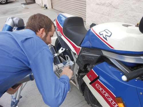
The profile of this motorcycle’s heat shield has been tested and refined for optimum performance. Any deviation to the intended profile can result in performance degradation or worse. Extremely tight tolerances over the entire profile are critical.
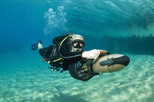
This underwater scooter is a great example of a beautifully sculpted shape that also has critical functional profiles. The flow around the scooter motor housing and through the propeller cage requires critical fluid flow design and manufacturing profile inspection to ensure excellent underwater performance. Comfortable and ergonomic handle grips and low profile steering structure must also have low drag through the water.

Unique product styling, though challenging to manufacture, often is what appeals to consumers and ultimately drives design innovation.
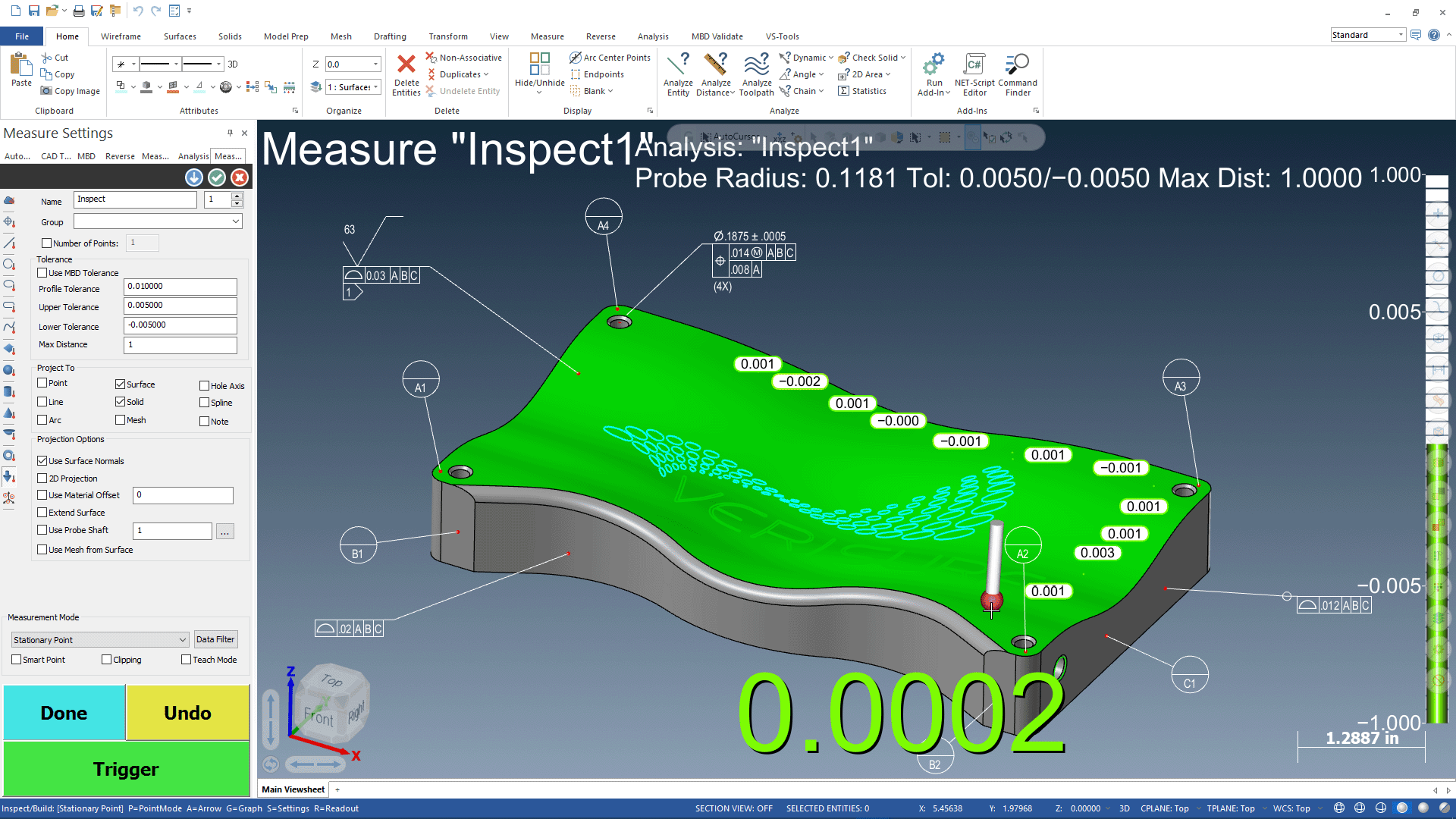
Using reverse engineering software, physical models can be accurately digitized and dimensioned using GD&T annotations to illustrate nominal measurements for inspection.
ALIGN
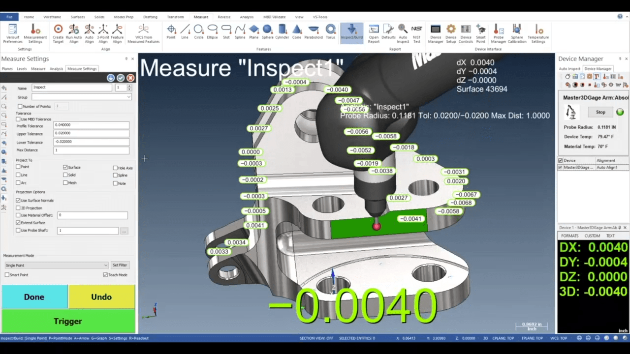
INSPECT
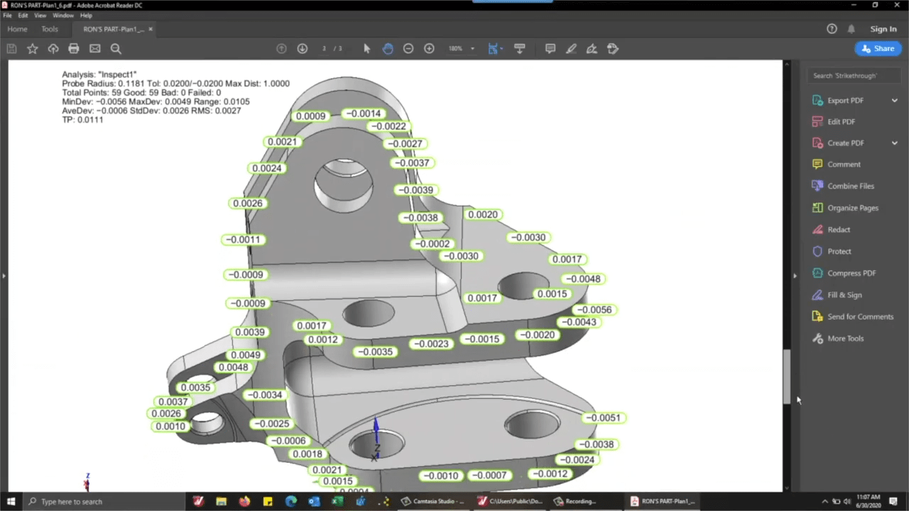
REPORT
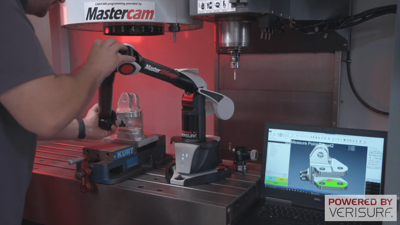
Align-Inspect-Report process. Align the CAD model to the part or tool using best fit alignment algorithms. Inspect the part to the CAD model nominal with model associated tolerances. Report the surface profile quality measurements with easily recognizable inspection locations and in or out of tolerance color indicators.