
Morgan Cars Builds on its Classic
Design with Technology and Innovation
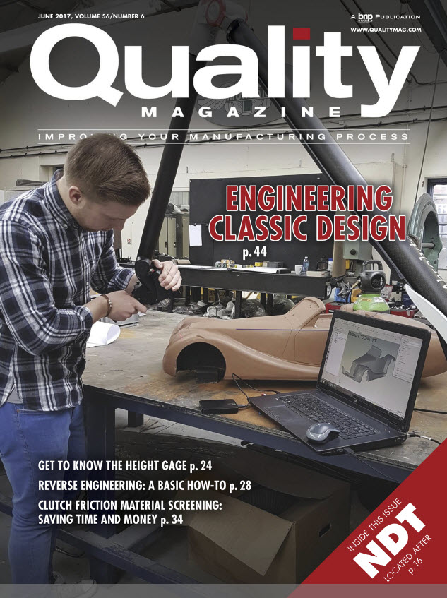
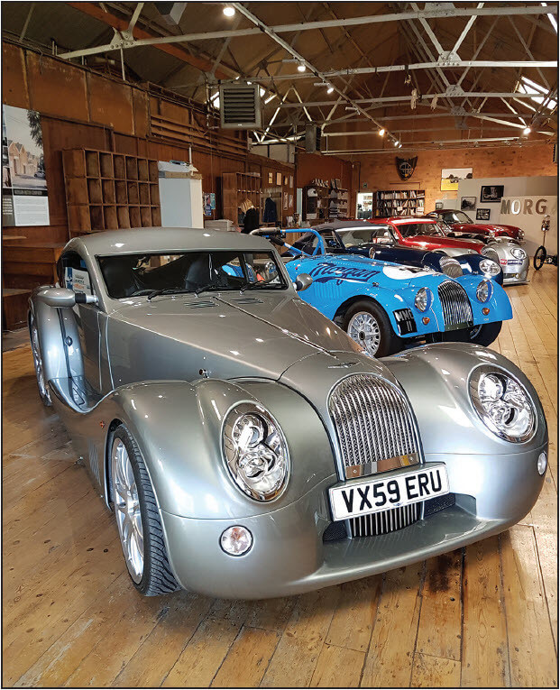
Today’s Morgan 4/4, a blend of classic styling, craftsmanship, performance, and technology.
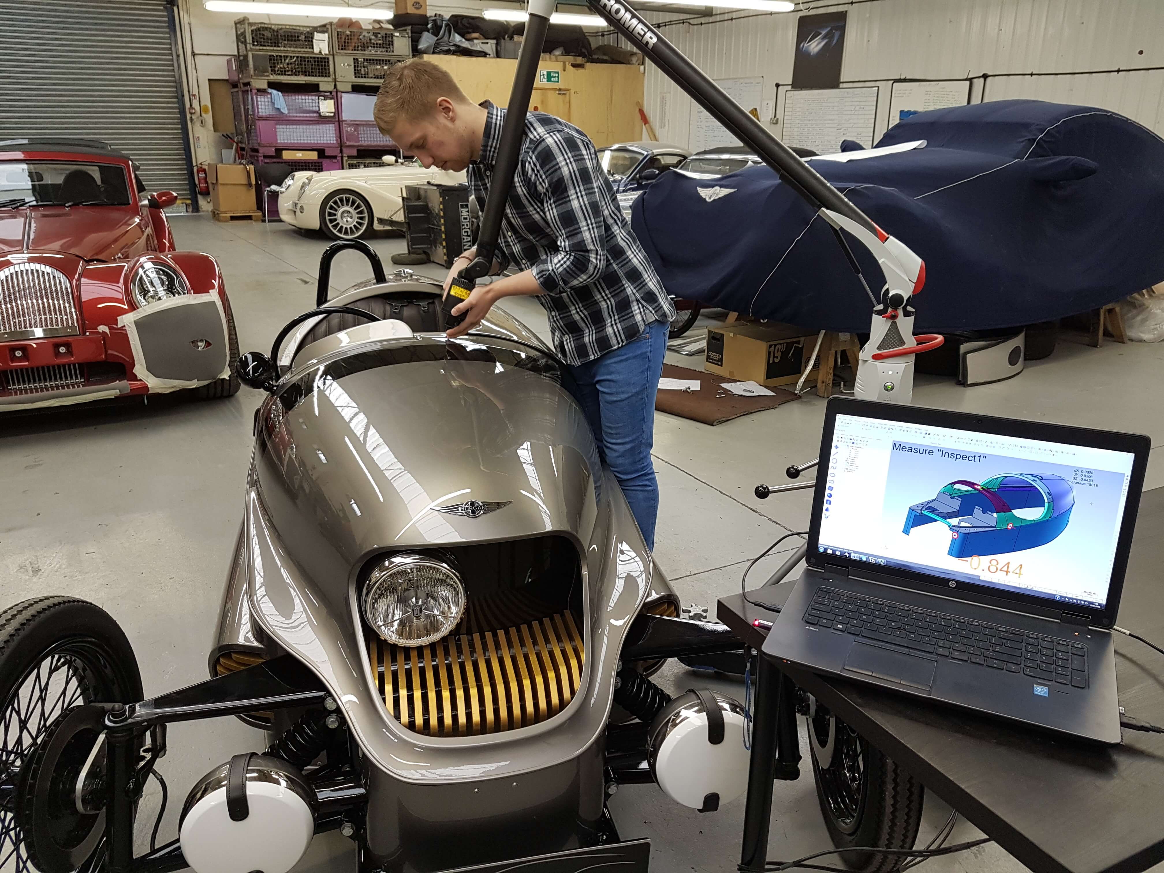
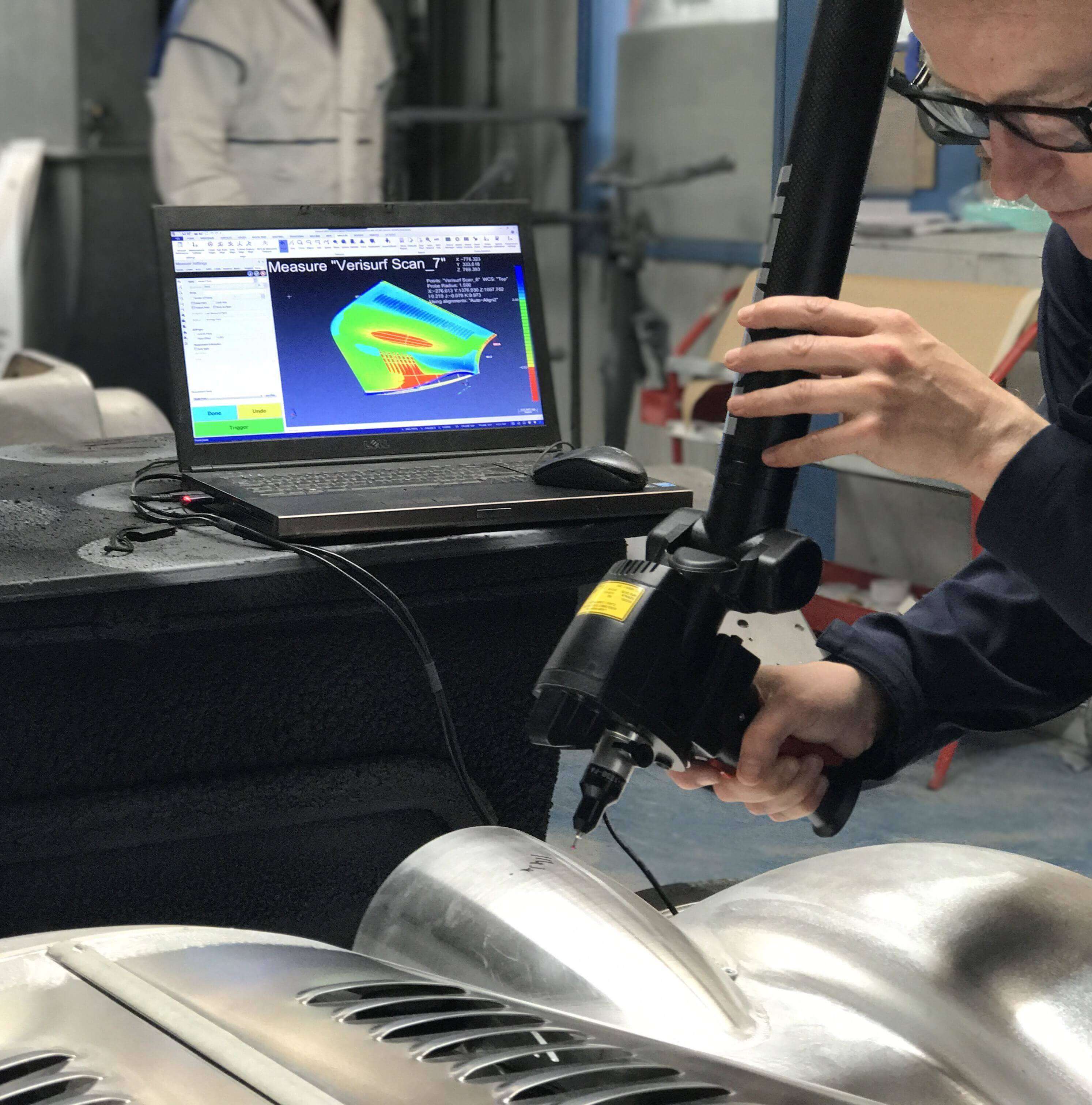
Handcrafted cockpit details of the Morgan EV3 are reverse engineered to a 3D CAD model using Verisurf Reverse Software and Romer portable CMM with laser scanner.
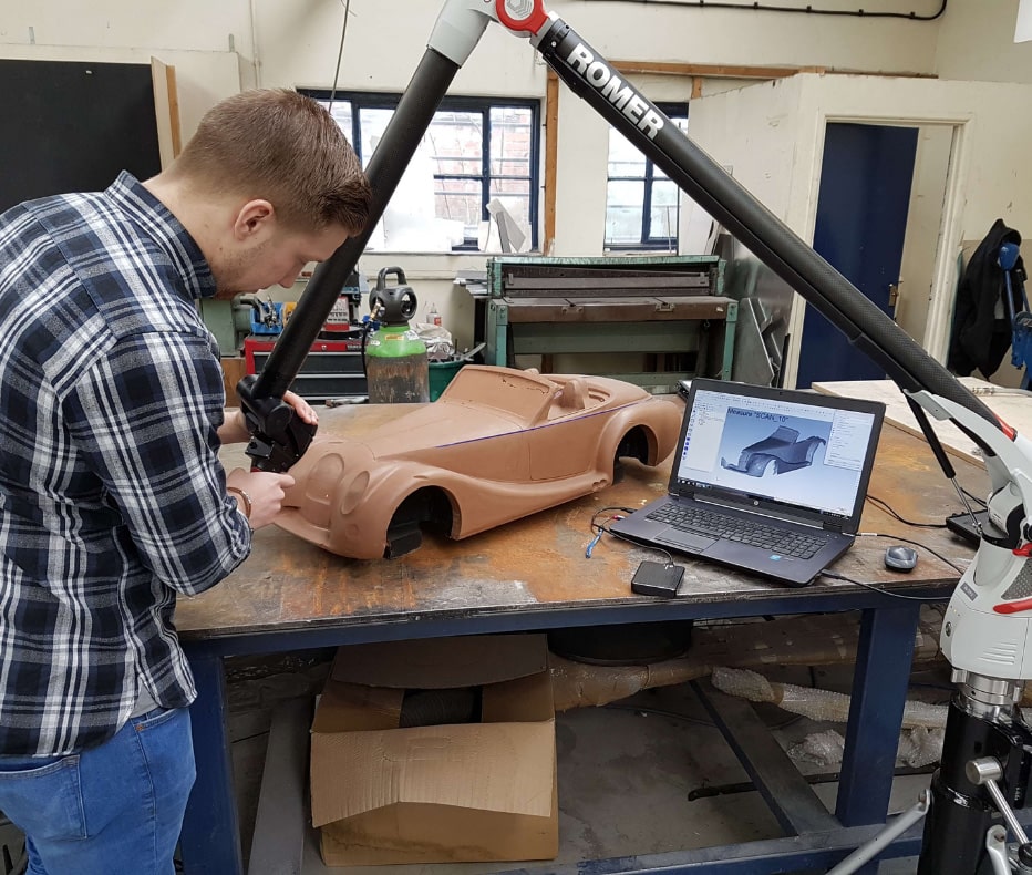
A traditional hand styled clay model of the Morgan 4/4 is scanned to create a digital design nominal of the surface profile.
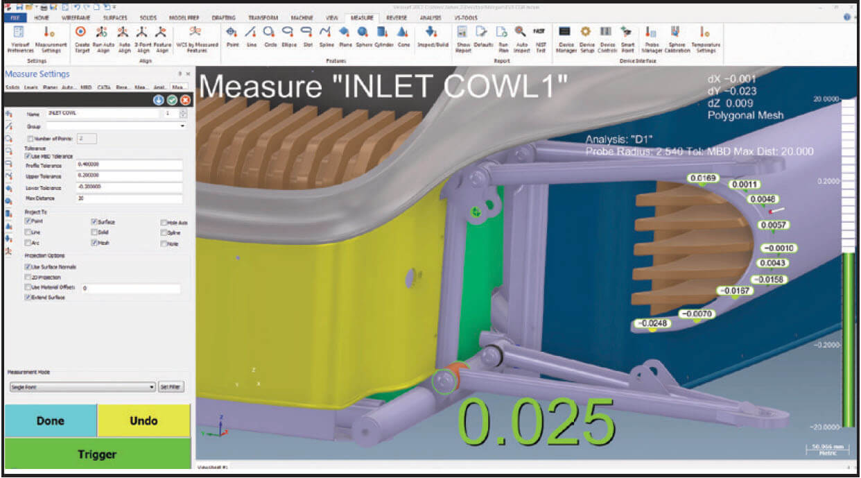
Finish fender assembly is inspected against 3D CAD model using Verisurf MBD (Model-Based Definition).
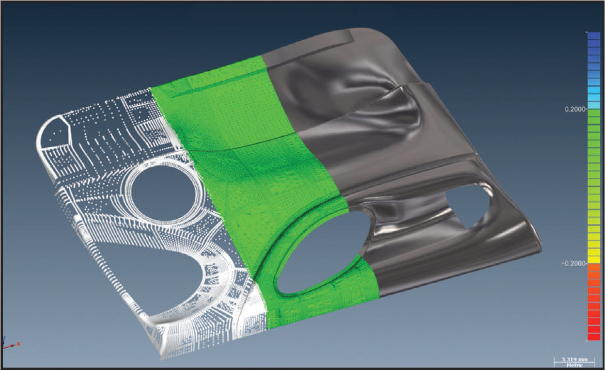
This image illustrates the Scan – Mesh – Model steps associated with the reverse engineering process. When 3D printing is involved you can save time by outputting directly from the middle step, mesh, as an STL file.
Precise positioning of fasteners, weldments and features can be directed using Verisurf Software to align the virtual CAD model with the physical part, then interactive positioning features ensure proper placement.
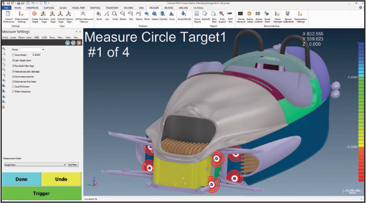
Easy alignment of the virtual CAD model with the physical part provides precise and intuitive targets for inspection.
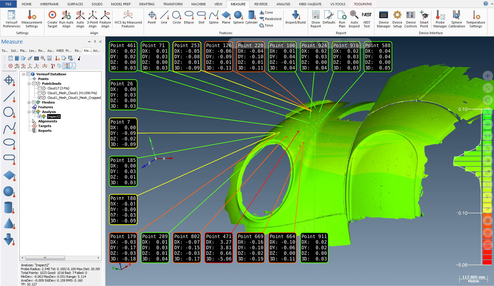
Real-time deviations from the nominal can be displayed numerically and through color variations.
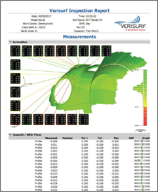
Quality inspection reports can be output in a variety of business and technical application formats.
Morgan has been producing high-quality handcrafted motor vehicles since 1909 and at the current Malvern Hills facility in Worcestershire UK since 1913. Today they produce their modern take on a British classic with a variety of traditional and modern vehicles, which embody Morgan’s heritage but embraces modern technologies. The traditional Morgan 4/4 is the longest running production vehicle in the world and has built up iconic status during that time. Today it is manufactured by a series of handcrafted and superplastically formed aluminum panels, a high-end process reserved for advanced aerospace applications and limited series exotic sports cars.
From its 3-wheeler origins emerges a striking vehicle in the shape of the Morgan EV3, New Electric design
The Morgan EV3 looks at the world of zero emissions motoring from an entirely different perspective. What if an all-electric vehicle was bespoke made, handcrafted and exhilarating to drive? The EV3 embraces new technology, delivers responsible driving excitement and continues to celebrate traditional British motor manufacturing. Morgan is showcasing the final pre-production phase car which reveals the restyled body and interior. Weighing less than 500kg, the all-electric 3 Wheeler has a range of 150 miles.
The evolution at Morgan is truly in the engineering of the cars. Graham Chapman, Technology Manager, has been instrumental in deploying new technology to build a greater understanding of the existing processes and developing new methodologies for future builds. Part of that modernization plan was to ‘digitise’ certain key characteristics of their chassis and body structures. “We were looking for a solution that was easy to use but provides the high-end functionality to deliver quality scans and inspection data that can be engineered to meet our exacting standards here at Morgan Cars. Morgan is a traditional method car builder but that does not mean we reject new technologies to achieve our goals of a ‘British Classic,” said Graham.
After evaluating processes and considering viable solutions, Verisurf Software was selected as the metrology software application along with the Hexagon Romer articulating scanning arm. The software/hardware combination provides Morgan with a user-friendly digital route from hand-built components and assemblies to the CAD engineering team. The engineers can then produce up to date CAD designs of traditional legacy car platforms. This provides great insight into the current build process and gives a planning method for repeatability.
Global standards and approval requirements impose great challenges on the design of new vehicles; the automated measurement solution provides the dimensional controls that is a must for any modern car manufacturer. The scanning and reverse engineering application is also deployed for prototype design and build. Scanning clay scale models from the designers capture the key dimensions and styling cues from which to start the engineering process. “The automated measurement solution has been a huge asset to the engineering team here at Morgan. It provides us with an array of functionality to achieve our goals,” said Tom Morris, CAD/Technology Engineer. “And with the flexibility of a common software application running across our development and manufacturing teams there is no project we can not achieve,” added Morris.
Model-Based Workflow Maintains Digital Continuity
Whether it is Boeing or a traditional automotive manufacturer like Morgan Cars, a Model-Based Definition (MBD) workflow is key to maintaining data integrity and relevance as part of the overall design and manufacturing process. For Morgan, a key requirement in selecting a measurement solution was, it had to be based on a CAD platform. When using MBD, the CAD model is the nominal to which all parts
are measured and inspected against, keeping the all-important digital thread intact—from design to manufacturing to inspection and quality reporting. Everything that defines the part exists in a single digital archive, including how to manufacture and inspect the part.
Morgan has specific process and workflow requirements that must be maintained, all while improving quality, consistency and overall production efficiency of their handcrafted cars. These include three discrete processes all tied back to a CAD model and all requiring in-depth measurement, processing, and analysis.
- 3D Scanning and Reverse Engineering
- Tool Building and Assembly Guidance
- Automated Inspection and Quality Reporting
3D Scanning and Reverse Engineering
In order to capture classic features from early designs and handcrafted models, for which there are no CAD files, Morgan relies on a straight forward process. Using their portable CMM scan arm and Verisurf software, they follow three steps to commit the designs to a CAD model.
1. MEASURE
The portable CMM scan arm is used with the “MEASURE” software module to measure and capture 3D features and surfaces as point clouds in the software, including planes, cylinders, cones, spheres, lines, splines, circles and slots. As the term point cloud infers the collected data is a group of relative points in space without any connecting structure or geometry between them.
2. MESH
The “REVERSE” software module connects the dots of the point cloud data with a watertight mesh. This includes multiple mesh alignment and merging, filtering points, smoothing surfaces and filling holes in the mesh. For some applications, a clean watertight STL mesh file is all that is necessary for rapid prototyping and additive manufacturing.
3. MODEL
To work with the data as a 3D CAD model the “REVERSE” software module converts STL mesh into 3D NURB surfaces; the “CAD” software module then performs surface modelling and solid modelling with GD&T associativity for model-based definition. Solid Models are often required to support modern manufacturing processes such as jig, fixture, and tool building, CNC machining and model-based inspection. Tool Building and Assembly Guidance Once the CAD design is complete the “MEASURE” software module is once again utilized to build precision layup tooling and guide assembly of weldments and other critical features. The process is straight forward and completed in three primary steps:
Tool Building and Assembly Guidance
Once the CAD design is complete the “MEASURE” software module is once again utilized to build precision layup tooling and guide assembly of weldments and other critical features. The process is straight forward and completed in three primary steps:
1. ALIGN
The “MEASURE” software module guides the user through alignment of the virtual part or tooling fixture CAD model to the physical part or tooling fixture being built.
2. BUILD
The “BUILD” software module displays real-time distance to the desired position with directional arrows to guide the user to the precise position to set a detail, drill a hole or weld a bracket.
3. ASSEMBLE
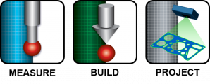
The “PROJECTION” software module programs and drives laser projectors that guide users through the assembly steps. Projected guided assembly data ensures precise positioning of parts in the proper assembly order.
Automated Inspection and Quality Reporting
Using MBD the CAD model is the nominal, in essence, a virtual ‘golden part’ from which all parts are compared. Because Verisurf Software is based on a CAD platform, Geometric Dimensioning and Tolerancing (GD&T) data can be added or edited to further define the part nominal. Once the quality inspection criteria have been set the inspection and reporting process is once again, three steps:
1. ALIGN
Using the “MEASURE” software module the physical part to be inspected is aligned with the virtual CAD model. Alignment targets placed on the CAD model guide the inspector through the entire alignment and inspection process.
2. INSPECT
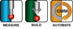
The “BUILD” software module is used again but this time to guide the inspector through an automated and repeatable inspection routine. The software provides real-time visual and audible indicators combined with color deviation displays to provide instant part quality feedback.
3. REPORT
The “AUTOMATE” software module is used to create repeatable automated inspection plans and generate custom reports in industry standard formats with GD&T constraints, color deviation maps and in or out of tolerance indicators for analysis.
Solution Criteria
For Morgan Cars, selecting the right solution required an objective internal evaluation of what they wanted to accomplish, followed by a list of criteria questions:
- Is the measurement and inspection software based on a CAD platform, including 3D solid modeling?
- Does it import and export all CAD files and models seamlessly?
- Will it import and allow annotation of GD&T data for complete model-based definition (MBD)?
- Is the software an open measurement platform that can connect with any brand or model CMM or scanner?
- Does it have the flexibility and embedded tools to handle the range of applications and inspection data, from manual contact probing to non-contact point clouds?
Morgan Cars is a perfect example of a company with a heritage of timeless design, styling and true handmade craftsmanship, embracing technology on their terms. The result is beautiful.
##
About Morgan Motor Company
The Morgan Motor Company Ltd. was established in 1909 by H.F.S. Morgan with the design of the Morgan three-wheeler. A four-wheeled model began production in 1936, and Morgan cars have long become famous the world over for their unique blend of charisma, quality materials, craftsmanship, and performance. You can learn more about the Morgan Motor Company Ltd at www.morgan-motor.co.uk.
Verisurf Software, Inc.
Verisurf Software, Inc. is an advanced three-dimensional measurement solutions company committed to delivering advanced computer-aided inspection and reverse engineering solutions. Verisurf software helps manufacturers of all sizes and industries produce higher quality products in less time and at a lower cost with automated, Model-Based Inspection processes. For more information, visit the Verisurf website at https://verisurf.com.
About Morgan Motor Company
The Morgan Motor Company Ltd. was established in 1909 by H.F.S. Morgan with the design of the Morgan three-wheeler. A four-wheeled model began production in 1936, and Morgan cars have long become famous the world over for their unique blend of charisma, quality materials, craftsmanship, and performance. You can learn more about the Morgan Motor Company Ltd at www.morgan-motor.co.uk.