
Tech Tip – Impeller/Propeller Measurement
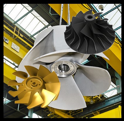
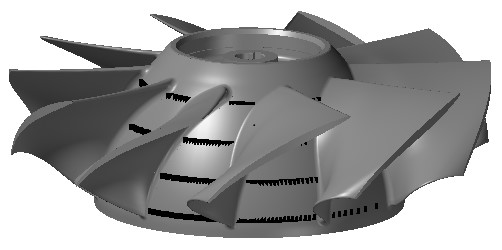
Impellers and Propellers come in all shapes and sizes, which offers unique challenges to Inspection or Measurement (for Reverse Engineering applications). However, Impeller/Propellers do offer common features that can be used for collecting the measurement data you require.
Since Impeller/Propellers always have a flat surface and a centerline axis aligning to the Propeller is simple and enables the operator to utilize different measurement methods offered in Verisurf.
Depending on your specific application, Inspection or Reverse Engineering, the measurement method you choose may vary. This Technical Tip will outline the different measurement methods available and highlight the benefits of each method to assist you in determining which method will give you the best results for your particular application.
What are your measurement requirements?
Your specific application will determine which measurement methods and techniques will be ideal for you, the following paragraphs will outline the Measurement methods dependent upon two common applications; Inspection (verifying the existing part to the CAD Model – CAD model required) or Reverse Engineering (CAD model does not exist, measurements will be used to create a CAD model).
When performing an inspection there may be key areas of the part that must be inspected and evaluated, whereas the point measurement for Reverse Engineering will require a much denser pointcloud to ensure the part is accurately defined. This Technical Tip only addresses the best methods for collecting the pointcloud data. For more details on using Reverse Engineering in Verisurf see the Reverse User Manual in the Verisurf dropdown.
Align to the Part
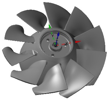
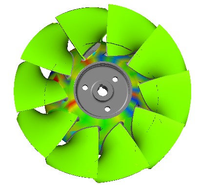
Before taking any measurements for Inspection or Reverse Engineering you will need to align your measurement device to the part. If a CAD Model is available using the AutoAlign process will easily align your device; for alignments without a model measure the features on the propeller that the blueprint designates as Datums and select Feature Alignment to align. Example on right is aligned to the hub Plane and cylindrical center.
Measurement Methods
After the device is aligned to the CAD Model it is easy to use Inspect/Build to quickly and easily collect measurement data using the Measurement Settings and Measurement Filters dialog. Detailed information on Polar Slice measurement method is available in the Measure Manager User Manual in the Verisurf dropdown.
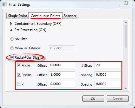
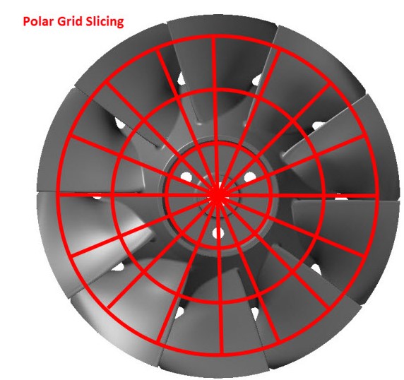
Radial – Polar Slice
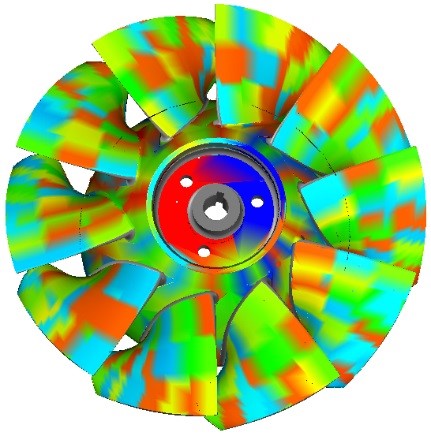
The Measurement Filter – Radial Polar Slice allows the operator to define a Grid measurement by defining “Slices” and “Radial” Offsets as shown in the following diagram, your Alignment must be set to the part axis and Plane.
Using the Z only would allow measuring about the hub in this example (shown right):
Benefit of Radial Polar Slice – collect point data in pre-determined slice and radial locations around the part. Defining a tight slice pattern aids the meshing processing for Reverse Engineering.
Drawback – points are measured whenever the pre-defined grid is crossed by the measurement probe, depending on the operator and the device being used data points may be dense in one direction and sparse in another; more filtering required for good results. When using a Laser Scanner, the part must be measured using multiple scans perpendicular to each other for the best results.
Predefine your Grid using Surface Points
Creating surface points requires a CAD model and is ideal when Inspection measurements must be taken in specific areas or when multiple parts will be inspected. This method requires some pre-planning, however, once complete allows quick and consistent inspection of duplicate parts and reporting in pre-defined formats.
Using the Verisurf Surface Grid tool the operator may create a unique Grid for each surface selection if required, or multiple surfaces may be selected to receive a common Grid pattern, see the illustrations on the next page.
Create the Surface Points on the part as required.
The Surface Grid dialog (right) gives you a variety of controls for creating Surface Points.
Draw As: – controls the display of the Surface Points.
Length – activates depending on the point style selected.
Projection – Surface points are created relative to the selected Surface (UV Distance or UV Number) or by the active CPlane.
Parameters – based on the selected Projection method, UV Distance is the distance apart of the points on the surface, while UV number is a number of points on each surface in each direction (U, V). CPlane allows the operator to select XY in the active CPlane.
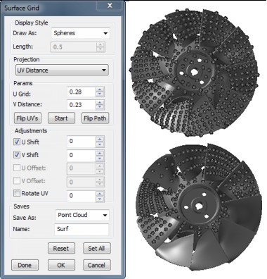
Flip UV – allows the operator to select the direction of the Surface Point vector when required.
Start – allows the starting point to be reversed when using the Path is selected in Draw As has been selected.
Flip Path – changes the direction of the Path direction similar to Flip UV.
When the dialog is open and a surface selected these spin controls are “live”, the operator can see the points being created.
Adjustments – provide the ability to “Shift” the starting point of the Grid.
Save – when OK or Done is selected how would you like the points stored, for this application we will select Scan, this creates an Analysis Object in the Data Tree.
Name Field – provides the operator the ability to name the Surface Points, Scan or Cloud for the Data Tree.
Create an AutoInspect Plan to Measure Surface Points
This method is commonly referred to as ‘Search and Destroy’ for Verisurf’s ability to measure only pre-defined Surface Point ‘targets’. Using the Analysis Group, created by the Verisurf Surface Point Grid tool in the previous paragraph, create a Report in the Measure Manager. This Report should only have your Surface Points as defined using the Verisurf Surface Grid tool.
In the Verisurf Report Manager double left mouse click on the Analysis Group and define how to measure (turn off Guided, this displays all targets and allows for Search and Destroy) and set the Threshold to a reasonable value (too small of value can slow measurement process). See also the AutoInspect User Manual in the Verisurf dropdown for details on measuring using AutoInspect.
Measure using AutoInspect
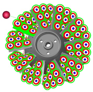
Select AutoInspect from the Measure Manager Toolbar, in the AutoInspect controls select Clear All, then choose Run AutoInspect, using your device measure the Surface points shown (they should appear as targets, once measured they will disappear). When all Surface Points have been measured, create a Report, this AutoInspect Plan can now be used for measuring additional parts.
Benefit of Surface Grid Points – Points can be measured in the same location and same configuration from one blade to the next. ‘Search and Destroy’ provides a great visual guide for the operator while measuring.
Drawback – requires a CAD Model.
Verisurf Software, Inc.
Verisurf Software, Inc. is an advanced three-dimensional measurement solutions company committed to delivering advanced computer-aided inspection and reverse engineering solutions. Verisurf software helps manufacturers of all sizes and industries produce higher quality products in less time and at a lower cost with automated, Model-Based Inspection processes. For more information, visit the Verisurf website at https://verisurf.com.