8 Reverse Engineering Best Practices You Should Know for Achieving Quality Results
With over 25 years engaged in various measurement and digitization projects and development of complimentary software tools, here we share some reverse engineering best practices. These will help any practitioner achieve quality results faster and with fewer “do-overs.” Add these useful guidelines to your skill set to improve your reverse engineering repertoire.
Best Practice #1:
Assess the most important features to develop your alignment
Trust your manufacturing experience to identify the primary, secondary and tertiary datums you’ll select for alignment. Items such as base planes and primary circles as a rotation point are commonly used. This practice assures that all subsequent features measured have a relationship back to selected, principle alignment features.
Best Practice #2:
Develop an alignment as early as possible in your R.E. workflow
After your principle alignment features are identified, use them to perform a Feature Alignment. This accomplishes 2 things. It squares up your views so that the Top View looks identical to what you are seeing in front of you on the surface plate. It will help to keep the UV grid of the surfaces from being rotated. If the UV grids are not “square” to the view that solid modeling operations and trimming operations may fail.
Best Practice #3:
Get your drift/common points down to maintain alignment
Unless the part being reverse engineered is a simple block, it may take some time to complete all the work. More time required to complete 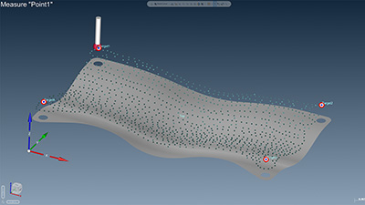 the reverse engineering process invariably results in the loss (or degradation) of the alignment from multiple factors. Getting back to the exact alignment by doing a new Feature Align is a near impossibility because you won’t measure the features in the exact way you did before. For this reason, try to get 3-6 “nests” glued to the part. Aligning to nested points assures a higher level of accuracy when probing points for an alignment.
Best Practice #4:
When Surface Patching, measure periphery points first
As illustrated here, always measure the outside edges first. The rationale behind this recommendation is that when you finally filter this pointcloud to eliminate overlapping or proximal points, you can be confident that the peripheral points won’t be eliminated. You’ll want those points undisturbed to help the surface patch maintain accuracy around the entire edge. If there were a gap in the peripheral points, the surface could lift or dip in that region.
Best Practice #5:
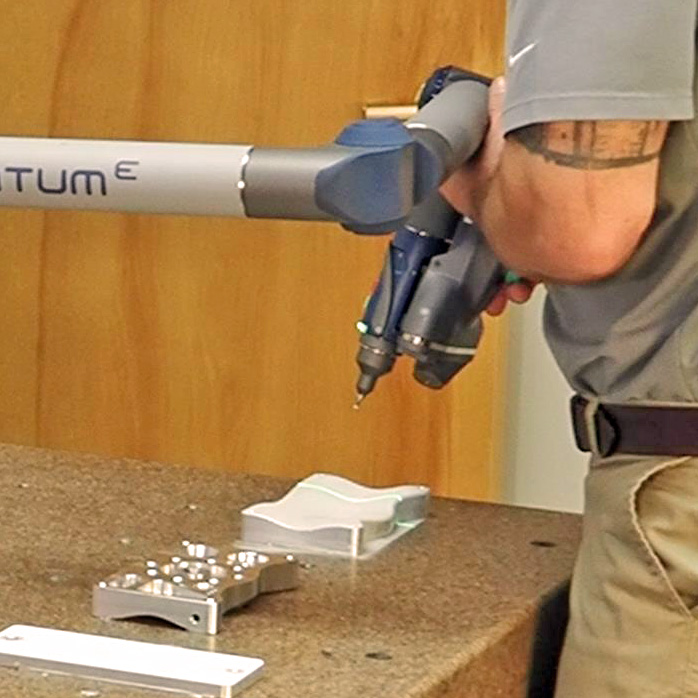
Use your measuring device to verify your RE results
After creating your surface (or surfaces), you can double check your newly reversed items using your measuring device. This assures that your surfaces are probe-comped correctly and that they are accurate to an acceptable deviation value.
Best Practice #6:
Analyze measured points (or pointclouds) to the new CAD entities to double-check your results
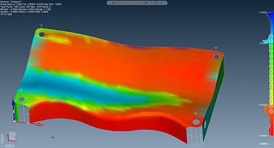 Much like using your measuring device to double check your accuracy, you can use your software to analyze the points that created the surfaces to the surfaces created. This may help to identify areas that may need more points or areas where re-measurement may be needed.
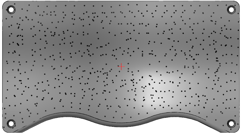
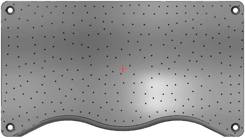
Best Practice #7:
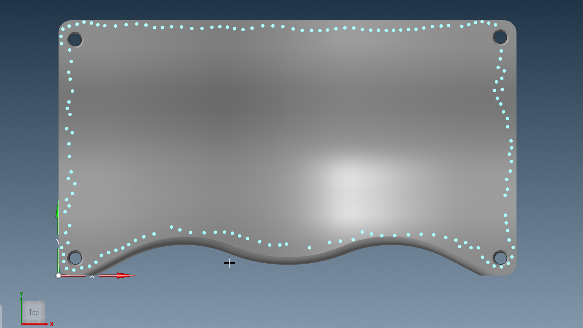
When scanning, less can be more
It is important to remember that if there are points that are stacked on each other within a couple of thousands that you will probably end up with a dimple in your surface. When reversing smooth gradual transitioning surfaces less IS better. On the left image below, there are many overlapping points. On the right, the pointcloud has been filtered from 715 points to 301 points. Having less data will save time when your CAD system is saving, exporting or creating new surfaces.
Best Practice #8:
Scanning WITH probing may be the better route
Many new users of measuring equipment may feel that the scanning of a complex part can be converted into a CAD model if they have scan data on every surface. This may be an incorrect assumption. Scanning may not work well for a few different reasons. Thin wall conditions may not yield a 3D mesh that is usable. Scanning a hole may not capture valid data due to the scanning angle. Some features are much easier to measure as features. If you are scanning a large, known planar surface, it could be measured as a plane in a fraction of the time that it would take to scan it.
We hope you find these reverse engineering best practices useful and that they are helpful in improving your reverse engineering skills.
Reverse Engineering Software Products

Verisurf Reverse Engineering Articles