
The GD&T Model
Read this story in Quality Magazine HERE
Story written in collaboration with Quality Magazine, October 2012, Volume 51/Number 10
What You Need to Know about Model-Based GD&T in the Manufacturing Enterprise
Model-based Geometric Dimensioning and Tolerancing (GD&T) is powerful digital intelligence that can automate and improve quality across the entire manufacturing enterprise. A snapshot of the manufacturing companies implementing it and involved in the standards process points to the growing importance of this 3-D digital manufacturing technology: Spirit AeroSystems Inc.; Raytheon Missile System; Northrop Grumman Corp.; Caterpillar Inc.; The Boeing Co.; Lockheed Martin Aeronautics Co.; Ford Motor Co.; General Motors Corp.; Rolls-Royce Corp.; GE Aviation, Goodrich Aerostructures; Bombardier Inc.; BAE Systems; Rockwell Collins; and Eaton Corp.
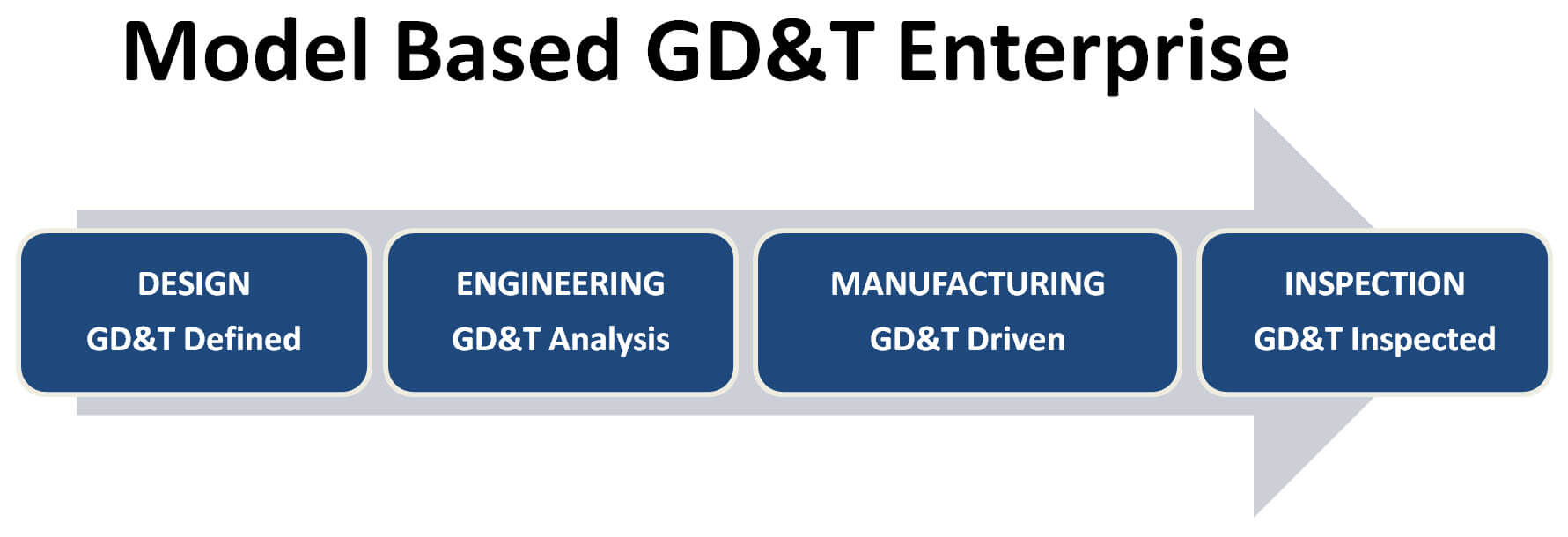
GD&T can automate and improve quality across the entire manufacturing enterprise. Source: Verisurf
The Model-Based Enterprise
The Model-Based Enterprise (MBE) organization is a great source of information and defines MBE as “an integrated and collaborative environment, founded on 3-D product definition (model-based definition) shared across the enterprise, enabling rapid, seamless and affordable deployment of products from concept to disposal.” They state that “The practice of using 2-D drawings as the master deliverable in the design process is fading fast, as many companies are adopting a new approach called MBE, where the 3-D model is the central source of all design information. A key driver to this trend is the development of new standards for 3-D model annotation which specify that 3-D drawings now include all information to satisfy the needs of downstream users.”
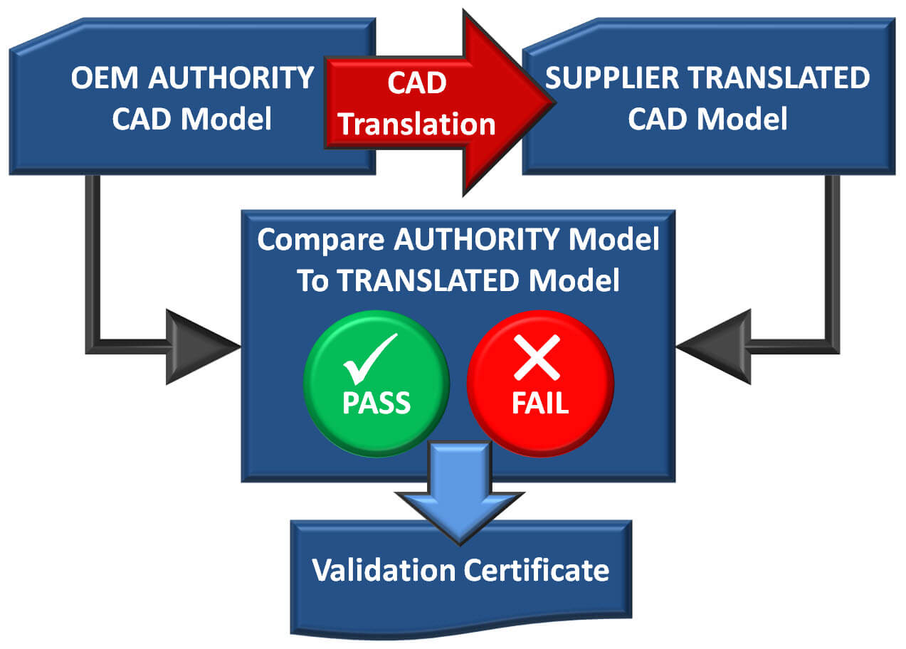
CAD translation validation is performed by comparing the authority CAD model to the translated CAD model and is documented with a tamperproof validation certificate submitted with the first article inspection report. Source: Verisurf
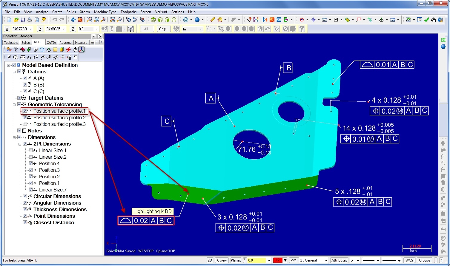
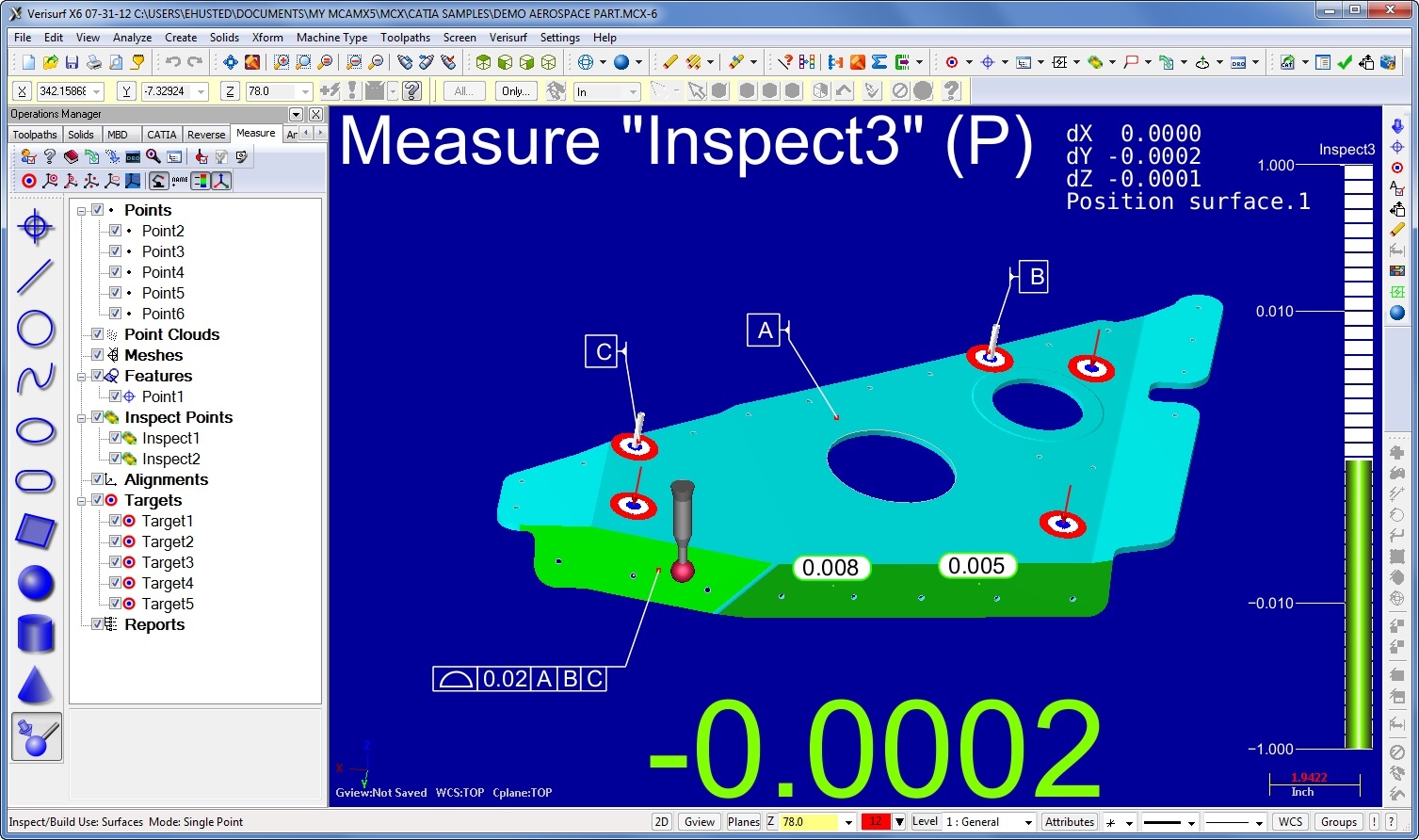
Using inspection software like Verisurf with the ability to import model-based GD&T data from suppliers can save many hours of entering model-based GD&T information by hand. Source: Verisurf
Technical Tips
- The more CAD file formats your inspection software can import, the more customers you can better support.
- The inspection software’s ability to connect to any brand of measurement device enables you to select the right CMM or 3-D scanner.
- A common software platform that supports all major CMM and 3-D scanner Model Based Enterprise brands can reduce training and support costs.
Design Phase: Defines GD&T to ensure the product meets specifications. GD&T provides a consistent, sound method for communicating design intent.
Engineering Phase: Simulates GD&T of the product assembly variation and performance. Virtual simulation of the entire assembly of parts under max/ min variation conditions identifies assembly issues before manufacturing. Virtual simulation identifies key characteristics critical to assembly and operation. Reduce costs by identifying non-key characteristics and relaxing their tolerances.
Manufacturing Phase: Guides the selection and management of manufacturing processes.
Inspection Phase: Specify inspection process for effective assessment of the manufacturing process and end product quality. Facilitate gaging requirements and automate coordinate metrology. Define, monitor and report on statistical process control (SPC) of key characteristics. Three-dimensional SPC findings can be communicated back to the design phase for closed-loop continuous improvement.
Maintenance Phase: Maintenance, repair, and overhaul (MRO) processes reference GD&T while inspecting the product for wear and reassembly. LOng Term ARchival (LOTAR) for sustainment of product until end-of-life requires three technology life cycles be considered and are product data for at least 50 years, the data storage for about 10 years and the software application for about three years.
Model-based GD&T Product Definition Data: Also known as Product Manufacturing Information (PMI). Denotes the totality of data elements required to completely define a product. Product definition data includes geometry, topology, relationships, tolerances, attributes and features necessary to completely define a component part or an assembly of parts for the purpose of design, analysis, manufacture, test, and inspection. See ASME Y14.41-2012 Digital Product Definition Data Practices or The Boeing Corp. D6-51991 “Quality Assurance Standard for Digital Product Definition,” which specifies requirements for their global supply chain.
Geometric Dimensioning and Tolerancing: GD&T is a system for defining and communicating engineering tolerances. The primary purpose of GD&T is to ensure a product is manufacturable, assemble-able and functional. The primary benefits of GD&T are: it encourages robust design with guaranteed assembleability and functionality; reduces cost through unambiguous communication and looser tolerances; and establishes 3-D metrology as a scientific process. See ASME Y14.5-2009, Dimensioning, and Tolerancing or ISO 1101 Geometrical Product Specifications.
Annotations: Dimensions, tolerances, notes, text or symbols visible without any manual or external manipulation.
Digital Element: Geometric element, feature, group of features, annotation, associated group, or attribute that exists in a data set.
Associativity: The established relationship between digital elements (as in “Semantic PMI”).
Model-based GD&T: The primary purpose of model-based GD&T is to clearly communicate GD&T across the manufacturing enterprise by associating GD&T to the 3-D CAD model and storing them and transporting them in the computer-aided design (CAD) file. The primary value of model-based GD&T is increased when time-to-market is critical, supply chains are dispersed, and establishing and monitoring quality is of high importance. Three-dimensional software applications that support model-based GD&T associativity can be identified by checking the user interface for three digital elements that are associated with each other. These are the GD&T annotation, GD&T annotation tree, and the GD&T associated model feature. Associativity between the elements is visually communicated by the highlighting of all three elements when selecting any one of the elements.
What to Look For
Look for these inspection software features when implementing model-based inspection into your manufacturing enterprise. The inspection software’s ability to import model-based GD&T from your suppliers can save many hours of manually adding the model-based GD&T. If your suppliers can only provide CAD models without model-based GD&T then make sure your inspection software has the ability to create model-based GD&T on imported 3-D models. The more CAD file formats your inspection software can import, the more customers you can better support. Model-based GD&T inspection software should automate the inspection process by displaying alignment targets and real-time display of part deviation to the associated surface tolerances. Audible and visual cues should immediately alert the user to part surfaces and features that are in or out of tolerance. Model-based GD&T adds inspection intelligence into 3-D CAD models and can automate the creation of repeatable inspection plans and inspection reports from the model-based GD&T. The inspection software’s ability to connect to any brand of measurement device enables you to select the right CMM or 3-D scanner for your application and empowers the buyer to negotiate with device manufacturers. A common software platform that supports all major CMM and 3-D scanner Model-Based Enterprise brands can also reduce training and support costs.
Model-Based 3D Engineering Standards
The objective of many software companies is to keep their customers within their suite of software offerings and proprietary formats by limiting their interoperability and support for open file standards. This practice limits the supply chain use of best-in-class software solutions, limits small- to medium-sized manufacturers access to 3-D model data, and ultimately results in higher prices. To improve interoperability and competition and lower prices, OEMs and government agencies are collaborating on ISO STEP AP242. STEP stands for STandard for the Exchange of Product model data and this new Application Protocol 242 is for managed model-based 3-D engineering, which will provide new capabilities needed to represent design and manufacturing data in a standard format. The capabilities will include new manufacturing features, material specifications, quality control information, and support for model-based GD&T. Testing is underway and publication as an ISO committee draft is scheduled for the 2012 fiscal year. The wide adoption of AP242 among engineering software application developers is expected based on the adoption of the ISO standards that are being replaced by AP 242. The new capabilities in AP242 will lead to reduced cycle time from design to production. It will also lead to reduced costs for the small manufacturing enterprises involved in that production since they will be able to use lower cost software applications based on standard interfaces rather than the high-end/high-cost applications used by OEMs. STEP AP 242, Managed Model-Based 3-D Engineering, is to be finalized by October 2012 and targeted to be an International Standard in July 2013.
CAD Translators & Validation (see flow diagram at left)
There are many CAD translators that support the translation of CAD models from one CAD brand to another CAD brand so make sure your CAD translators support model-based GD&T if you want to get the maximum benefit from the intelligence embedded in model-based GD&T. Boeing and a growing number of aerospace and defense OEMs are keenly aware of the possibility of CAD translation errors in Model-Based Enterprises and require CAD translation validation to eliminate any chance of incorrect parts being manufactured and installed from bad CAD translation. CAD translation validation is performed by comparing the authority CAD model to the translated CAD model and is documented with a tamperproof validation certificate that is submitted with the first article inspection report. Boeing’s D6-51991 “Quality Assurance Standard for Digital Product Definition” specifies this requirement for their suppliers.
The Growing Skills Gap
Manufacturing has a growing skills gap crisis. Kids don’t see manufacturing as exciting, parents don’t want their kids in factories, the current workforce is aging and retiring. To make matters worse the design and manufacturing industry has been speeding toward a fully 3D model based enterprise and implementing GD&T, while technical educators are still teaching traditional 2D drafting and blueprint reading.
A SpaceX inspector uses Verisurf software with a laser tracker to qualify a Falcon 9 rocket substructure.
“With our Model Based Inspection software we are looking directly at the CAD model with associated GD&T and the laser tracker measurement results reflected against the 3D model in real time. This makes the inspection process faster and reduces mistakes. We are not drawing free yet, but like the rest of the aerospace industry we are striving to implement model-based definition to achieve its many benefits.” Read the SpaceX article HERE.
Larry Mosse, Tooling Operations Manager
Space ExplorationTechnologies (SpaceX)
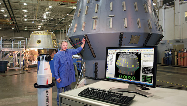
Inspection Software In Action – Gabe Draguicevich, Engineering Technologist, NAVAIR Advanced Measurement Systems and Reverse Engineering Lab. Source: Verisurf
“We’re trying to efficiently and effectively implement Model-Based GD&T into the Navy system. Having the ability to compare 3D scanner point cloud data to a 3D model and quickly display the deviation to associated surface profile tolerances is a powerful capability. Another great thing about our model-based inspection software is model-based definition, which lets us predefine GD&T on the model before inspecting the parts.” Read the NAVAIR article HERE.
Gabe Draguicevich, Engineering Technologist
NAVAIR Advanced Measurement Systems
and Reverse Engineering Lab
##
Verisurf Software, Inc.
Verisurf Software, Inc. is an advanced three-dimensional measurement solutions company committed to delivering advanced computer-aided inspection and reverse engineering solutions. Verisurf software helps manufacturers of all sizes and industries produce higher quality products in less time and at a lower cost with automated, Model-Based Inspection processes. For more information, visit the Verisurf website at https://verisurf.com.