
Scan It, Build It
The ability to scan a sample part and quickly move to fabrication
improves manufacturing efficiency and the quality of life
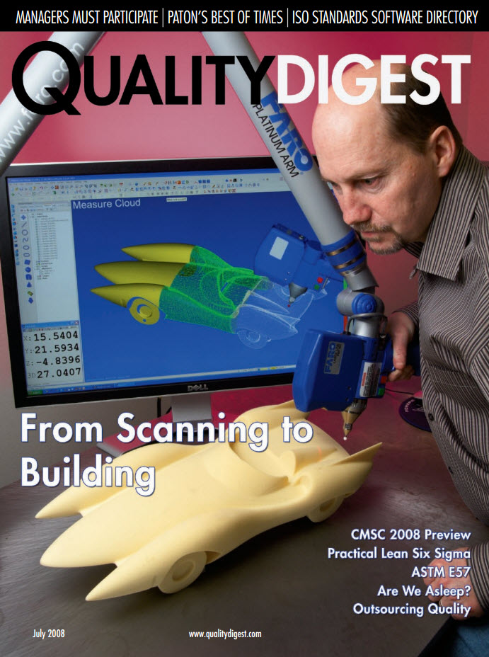
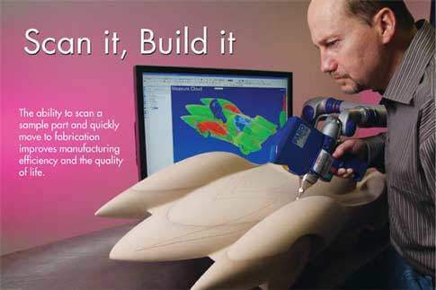
The ability to scan a sample part and quickly move to fabrication improves manufacturing efficiency and the quality of life.
Nick Moffitt is education manager at Verisurf Software.
Learn more at https://verisurf.com
When Gabe Draguicevich was asked to help fabricate a titanium hip implant based on CT (computed tomography, also known as CAT) scan data, he had to coordinate numerous technologies to complete the project. Because the CT data consisted of 2-D cross-sections, Draguicevich had to stack and align the individual scans to create a 3-D model, which he used to create a polygonal mesh in the form of a stereolithography (STL) file. After creating a prototype, he had to verify it against the original scan data, which was no mean feat considering that software capable of providing deviation analysis of the model surface to the STL file did not exist. Finally, Draguicevich created a wireframe model from the STL mesh to machine the final product. The entire process took approximately two weeks to complete.
That was 20 years ago. According to Draguicevich, “If I had the tools that are available today, I could have simply taken the CT scan data and created the STL mesh in one step, and then machined directly from the mesh. The data-processing capabilities of modern software have made the entire process painless compared to years past. Furthermore, I could have taken the finished piece and inspected it for accuracy using the original scan data as the reference. Any deviations could have been addressed by modifying the finished part in coordination with the inspection process.”
For years, the need to create surfaces has been a limiting factor in the ability to go from sample part to machined replica. Surfaces were used to create tool paths, which were in turn used to drive the computer numeric controlled (CNC) mill. Surfacing—part art, part science—is the process whereby scan data are converted into a mathematical representation of an object. It has long been the domain of expensive, specialized software and highly skilled users, for whom tribal knowledge and subjective judgment were necessary for success. With the technology available today, scan data can quickly be turned into a machinable mesh with little or no user intervention.
In basic terms, a mesh is a collection of 3-D points organized into facets according to some geometric configuration, typically triangles (triangular facets) or polygons (multisided facets). The most common example is an STL mesh, which first came into popular use as the file format for stereolithography. In comparison, a surface is usually defined parametrically (by an equation) or analytically (by control points). Because a surface is a mathematical description of a physical object, it is a more efficient form of representation than a mesh, which describes an object simply by enumerating a large number of points sampled from the part.
Although a surface is more efficient in many cases, a mesh provides a more accurate result. This is especially true when the goal is to replicate the as-built condition of the exemplar part. Using a high-density scanner, the surface condition can be captured in great detail. Surfacing the scan data would take additional time, require the skills of a trained operator, and introduce unnecessary complexity into the process. Most important, however, the surface would likely represent only an approximation of the actual part. An accurate surface developed for this purpose would be unnecessarily complex.
Meshes for the Masses
A number of technological advances have made the scan-to-part process available to the mass market. These include ready availability of portable scanning systems (such as articulating arms), coordinate measuring machines (CMMs, laser trackers, improvements in algorithms that provide quick and accurate development of meshes, and improved tool-path techniques that allow machining directly from splines or mesh surfaces. One of the most significant factors is the improvement in computational efficiency enabled by fast computers, cheap RAM, and large hard drives that have made it possible to process enormous point clouds and meshes.
When a tool path is put on a surface, the result is a series of line segments – the lengths of which are controlled by a chordal tolerance (the maximum allowable distance from the line segment to the surface). The high density of mesh data that can be processed today means that mesh facets now fall below this chordal tolerance. The result is that meshes can now be made smooth enough to substitute for a surface.
An all-in-one Solution
The elements that compose the scan-to-part process include the ability to communicate with scanning devices; to efficiently create, edit, and smooth a mesh made from scan data; to create a tool path and post to a milling machine; and to verify the final product by comparing it back to the scan data through the use of real-time, 3-D inspection. These functions can be found in a variety of software products on the market.
One product, in particular, combines all of these elements into a single software program that uses a common model file for each step in the process. Verisurf software, integrated within Mastercam, allows users to accomplish the entire product cycle of scanning, meshing, machining, and inspection—all within a single application and using a single file. Originally developed to inspect complex aerospace parts to the CAD model, this software is now used for reverse-engineering, model-based tool building, and inspection.
Building to Meshes
The technological advances that make scan-to-part processes possible yield other benefits as well. These include the ability to build and inspect to meshes instead of surfaces. The “build” process integrates the use of a 3-D measuring device, such as a CMM or a laser tracker, with software that provides a real-time comparison of the measurement probe to the computer-aided design (CAD) model. Once the device is aligned to the physical basis of the CAD model, the software analyzes the spatial deviation between the actual part and its nominal position as defined by the model. Using this feedback, parts can literally be “indicated” into position, meaning that the measuring device acts as a dial indicator that allows the tool builder to make continuous and minute position adjustments.
Consider the problem of moving a large, multipart master model from one facility and reassembling it at another location. Prior to the digital age, plaster masters were the authority that defined the physical shape of an airplane. Typically, the process involves creating a reference system in which numerous tooling points are measured in the as-built condition. These points are then used to build the pieces back into their original relative positions at the new location. However, tooling points capture the geometry of the model at only a few discrete locations. If the pieces are not perfectly rigid, the assembly process suffers a loss of accuracy.
One alternative is to capture the entire surface definition in the as-built condition and to then use those data to build the pieces back into position. The problem with this process has always been the difficulty in creating an accurate surface definition of the model. Done correctly, this reverse engineering step is complex and time-consuming. However, with current technology, scan data can be used to create a mesh—quickly, accurately, and with minimal operator input. The mesh, rather than a surface, serves as the digital authority for the model definition. The entire physical surface of the model, rather than just the tooling points, can then be used to position the individual pieces.
Projecting the Image
Laser projectors – industrialized, high-accuracy versions of the tool that used to play laser-light shows – have been staples of composite manufacturing for almost 15 years. With their ability to project 3-D curves onto complex surfaces, laser projectors have virtually eliminated templates in many layout applications, especially the placement of composite plies. Interfaced to a CAD-based program, these projectors are very effective at visualizing CAD information in the physical world.
There is a fundamental assumption, however, that must be satisfied for laser projection to work correctly: that the physical surface onto which you are projecting matches the corresponding CAD surface. Otherwise, the projected laser light will overshoot or undershoot the correct placement, depending on the nature of the surface deviations and the orientation of the projector. For most applications, this is not a concern because manufacturing tolerances virtually guarantee that the surface will be close enough. As the technology gets pushed into more applications, however, the underlying assumption cannot always be guaranteed. The solutions to this problem are simple and novel.
For a recent project at a major shipbuilding facility, the challenge was to use a laser projector to display the intersection of a theoretical cylinder with a nominally spherical surface. As a test, the curve had already been laid out and verified using other means. Due to the nature of the surface deviations, the projection missed the mark by up to three-quarters of an inch.
The simple solution was to scan the surface using a CMM, create a mesh, and recalculate the intersection with the cylinder. The entire process took less than five minutes and produced a perfect agreement with the known data. The novel solution to this problem is provided by Laser Projection Technologies Inc., located in Londonderry, New Hampshire, in the form of the LPT100 using Verisurf software. In addition to projecting CAD information, the LPT100 is able to scan the surface to create a 3-D point cloud, thus allowing the system to verify, or even to redefine, the surface prior to projection.
From Vision to Reality
Applications of the scan-to-machine concept extend beyond industry and into the health sciences. Consider the advancements that have occurred in the process of creating a restoration for a dental patient. William Moffitt, professor emeritus, University of Maryland Dental School, describes the traditional process of creating a gold crown: After the patient is anesthetized, the problem tooth is ground down to create what is known as a preparation. The dentist then uses impression material to create a mold of the preparation and the adjacent teeth. Molds are made of both the upper and lower teeth, and a wax registration process is used to record the occlusion of the opposing teeth. The impressions are sent to a dental lab where they are filled with stone slurry, which sets into a solid model of the teeth. A technician next builds up a wax crown on top of the model of the preparation. The wax is then removed and used to create a metallic crown using the lost-wax method of investment casting. Finally, after approximately two weeks, during which time the patient wears a temporary crown, final adjustments are made and the permanent crown is cemented or bonded to the preparation.
Recent developments in vision systems, computer-aided manufacturing (CAM), and CAD can revolutionize the process. Once the preparation is complete, instead of taking an impression, the dentist performs an optical scan of the preparation and adjacent teeth using a small intraoral camera. Software converts the scan into a 3-D model, which the dentist can use to design the restoration, typically within a few minutes.
A dental database provides the starting point for each size and shape of the tooth. When the design is complete, the data are sent directly to a desktop CNC mill, which can fabricate a ceramic restoration in 10 to 20 minutes. After fitting and polishing, the restoration is bonded to the preparation. The total time for the process is typically less than two hours, and the cost is the same as a standard restoration.
Face-saving Measures
Beyond what the scan-to-part process offers in terms of manufacturing efficiency, perhaps the most compelling use of the technology is exemplified by the work that CimMed Inc., of Algona, Washington, is performing for the medical community. Steve Kidd, a long-time Mastercam reseller in Washington State, recently launched a new business that applies the same technology to burn victims that he has provided to the aerospace industry for years.
In 2007, CimMed worked with Harborview Medical Center in Seattle, Washington, to help the staff on the burn ward scan the face of a new patient who was scheduled for a skin graft the following day. The patient had been burned over his face and arms, and a special soft gel mask made of silicon was being prepared to facilitate healing and to encourage the graft to attach to the underlying tissue. This approach is referred to by other burn centers as the “Harborview method,” in recognition of its pioneering work in this area.
The traditional method for making burn masks requires that the patient be anesthetized, after which the occupational therapist covers the face with an epoxy resin, creating a mold of the face. After the resin is cured, plaster of Paris is poured into the mold and used to make a positive impression. This tool, in turn, is coated with a special silicone gel to create the healing mask.
Although scanning patients with lasers is not new, this is the first time that a patient has been scanned while on life support. Typically, the patient must visit one of the few centers around the United States that perform scanning in a special studio setting. CimMed was able to make the measurements using a portable laser scanning system. In addition to preventing further trauma to the patient, the proximity to the burn-center staff created a close collaboration and allowed the occupational therapist to ensure the quality of the final mask design. Because patients will often wear a hard, clear plastic version of the burn mask for up to 14 months, proper fit is critical.
Once the scan was complete and the model finalized, a positive tool was machined on a CNC mill in lieu of the plaster of Paris approach. The whole procedure can be completed in less than four hours, as opposed to the five days that are typically required.
Future Prospects
What do these developments mean for the future? Certainly, the need to develop surfaces will not go away any time soon; in many applications the scan is but a starting point, and an aesthetic, rather than a literal, representation of the sample part is paramount. However, the advent of lower-priced scanners, powerful computers, and simple, affordable, all-in-one software solutions means that companies will become more efficient and will be able to develop more innovative manufacturing techniques. And, if the past is prologue, more ways will be found to improve the quality of life.
##
About the Author
Nick Moffitt has been involved with various aspects of industrial metrology for more than 25 years. Educated as a civil engineer specializing in surveying and photogrammetry, he has worked as a software developer, product manager, technical writer, trainer, and contract measurement provider. He is currently Education Product Manager for Verisurf Software, Inc.
About Verisurf Software, Inc.
Verisurf Software, Inc. is an advanced three-dimensional measurement solutions company committed to delivering advanced computer-aided inspection and reverse engineering solutions. Verisurf software helps manufacturers of all sizes and industries produce higher quality products in less time and at a lower cost with automated, Model-Based Inspection processes. For more information, visit the Verisurf website at https://verisurf.com.