Path Generation Controls for Lines
Software Highlights – AUTOMATE – CMM PROGRAMMING
PATH GENERATION CONTROLS FOR LINE FEATURE
Verisurf simplifies the Approach and Retract Direction control on a Line feature by providing three options to the Generate Path dialog; Top, Left, and Right.
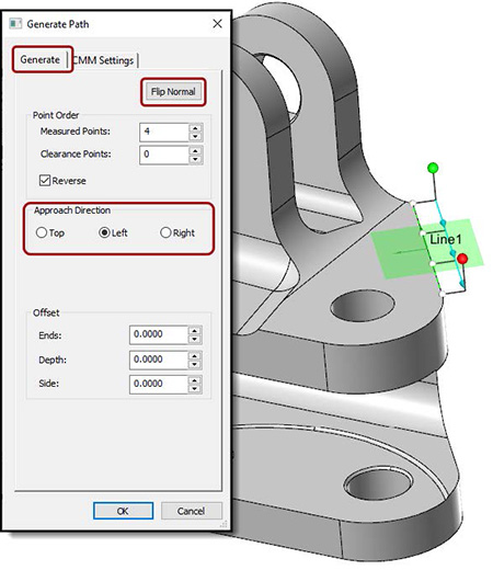
- Top is perpendicular to the nominal projection plane of the Line.
- Left and Right are parallel to the Line on the left or right-hand side.
The Clearance Feature Vector is in the perpendicular direction of the green translucent plane that represents the nominal projection plane of the Line.
- Select the “V” key with mouse focus the Line in the Automate Manager to turn on, increase size, and turn off the vector, axis, and plane display.
- Flip Normal can be selected in the Generate Path dialog to flip the Feature Vector direction.
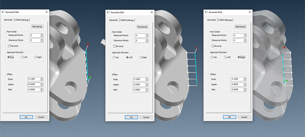
Approach and retract direction: Top, Left and Right options provide fast and easy workflow. Real-time visualization helps the user see how to cut cycle time and avoid collisions.
More on Line Features
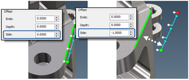
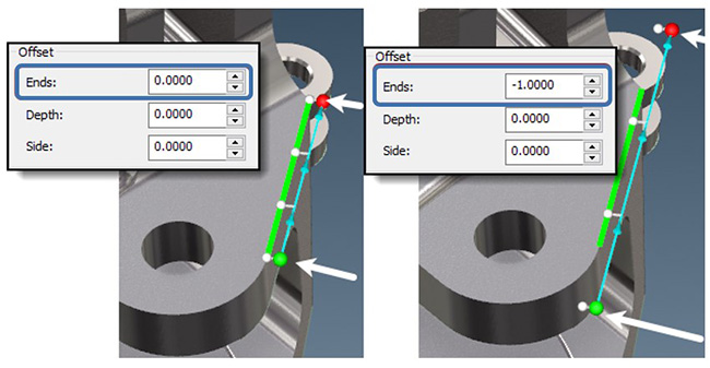
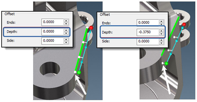
Offset
Offset values can be positive or negative; directions are based on the selected projection plane; in the illustrations below, the top surface is the projection plane.
- Ends – distance from the end of the selected CAD Line, used to adjust the length of the measured Line.
- Depth – distance perpendicular to the Line.
- Side – distance perpendicular from the Line measured on the projection plane.