
Software Highlights – CMM Programming
MIRROR PATH AND SET CAD ASSOCIATION IN A CMM PLAN
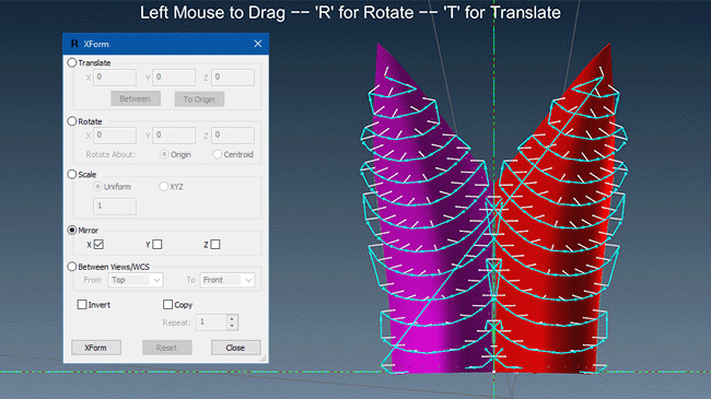
Mirror CMM Path in a Plan
The need to mirror a CMM path is not unusual, especially in aircraft and automobile industries, which typically have a left and a right hand mirror image of many components. In Verisurf Automate CMM Programming, you can easily create half a plan and mirror the Analysis (surface points) object to the opposing surface. This time-saving option also gives the user a quick way to associate the mirrored Analysis objects to their new entities.
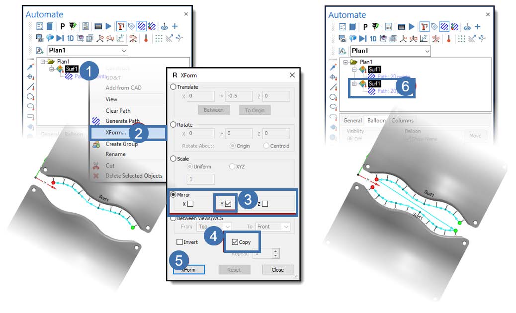
 In this example, we mirror an Analysis Object to the left side of a symmetrical part.
- Select the Analysis object in the Plan and open the speed menu.
- Select Xform to open the dialog.
- Choose (in this example) to Mirror the “Y” Axis.
- Select Copy.
- Select Xform to complete the operation.
- The dialog closes, and an additional Analysis object resides in Command Tree.
- Select the new Analysis object, rename it if required, access the speed menu, and select the Edit Projection Association.
- Select Clear Selection; this clears the current selection associated with the original Analysis object.
- Choose your Settings and then the Projection Association.
- Select OK; you are now ready to measure both sides of the symmetrical part.
Mirror the Plan
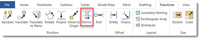
Mirror geometry right in Verisurf’s native, full-featured CAD
Edit Projection Association for CMM Path to CAD in a Plan
When creating Analysis Objects in a plan, the analysis is associated with its selected entity. Occasionally, the CAD Surfaces are edited after the Surface Points are added to the Plan (such as when there’s a design change). When this occurs, you must edit projection association for the Plan to measure and analyze correctly.
Edit CAD Projection in a CMM Plan
- Right-click on the Analysis object in the Plan and select Edit Projection Association… from the Speed Menu.
- The Edit Projection Association dialog opens (right); use the following controls to edit the current Projection Association.
-
- Find Closest – Associates the closest entity to the Analysis Object.
- Clear selection – clears all current selections.
- Project To – use to control the Analysis Object’s association to its intended entity.
- Use Global Analysis Setting – Pulls the Probe Comp from Preferences settings.
- Custom – Overrides Preferences to allow for user Probe Compensation Selection. It does not affect the Preferences setting.
- Probe Compensation – accounts for the Probe Radius according to the selected CAD entity. When Probe Compensation is applied, Verisurf determines the normal vector from the probe center (CMM Point) to the nearest nominal point on the CAD feature (Nominal Point) and subtracts the probe radius to determine the point-of-contact on the actual Feature (Actual Point). Deviations between the Nominal and Actual points is either form or build error.
- Projection Options – allows the user to utilize data embedded within the Model.
- Surface Normals – When selected (Default setting), use the surface Normals to project points to surfaces. If checking Use Surface Normals, make sure the Model’s surface Normals point toward the probe contact surface.
- 2D Projection – check this option to perform a 2-dimensional projection.
- Use Material Offset – this option is used to project inside or outside the material if required. Useful when measuring inner Mold Lines (IML) or Outside Mold Lines (OML).
- Extend Surface – used when measuring near the edge of a part, enables correct projection to surfaces near or on edges.
- Use Probe Shaft – enable to measure using a Probe Shaft; the numerical field defines the Probe length.
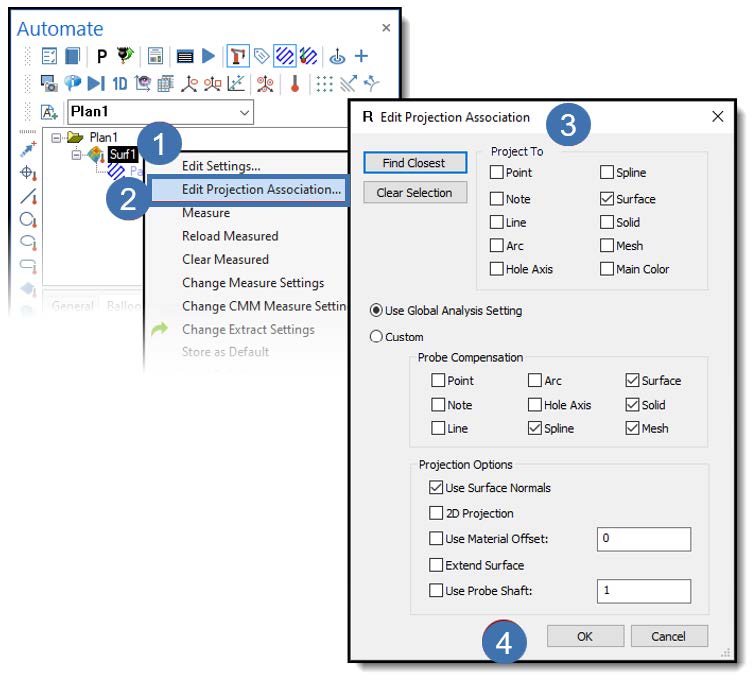
3. Choose your Settings and the CAD Associations required.
• Use Clear Selection as required during the selection process.
4. Select OK to save.