Software Highlights – CMM Programming
DYNAMIC SURFACE POINT
Verisurf AUTOMATE Dynamic Surface Point allows the user to create CAD surface points with simple mouse clicks for CMM path programming. These surface points can also be employed to create manual metrology discrete surface point targets or triggers.
 Using Dynamic Surface Point
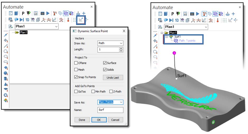
The following process is used within Automate to set up and define a Dynamic Surface Point measurement process.
- From the Automate toolbar, select Dynamic Surface Point to add the Surface Grid object to the Plan. (If no Plan exists, Verisurf creates Plan1 to hold Data created by this function.)
- As you move the cursor over the Model, the Surface Normal vector and a “+” cursor appear. The X, Y, Z, and I, J, K location displays as you move, and the Dynamic Surface Point dialog appears.
- Dynamic Surface Point dialog opens, allowing you to:
- Edit Vector display
- Change Project To settings
- Add GoTo Points
- In the Save As control, verify that the Plan is selected.
- Name the group as it appears in the Operations Tree.
- Select Done for each Point object required; the dialog box can remain open for multiple selections.
- Choose OK to close the function.
For more information about Dynamic Surface Point functions, see the Verisurf Analysis Reference Guide in the Verisurf Documents folder installed on the workstation desktop with Verisurf.
Details on Dynamic Surface Points Usage
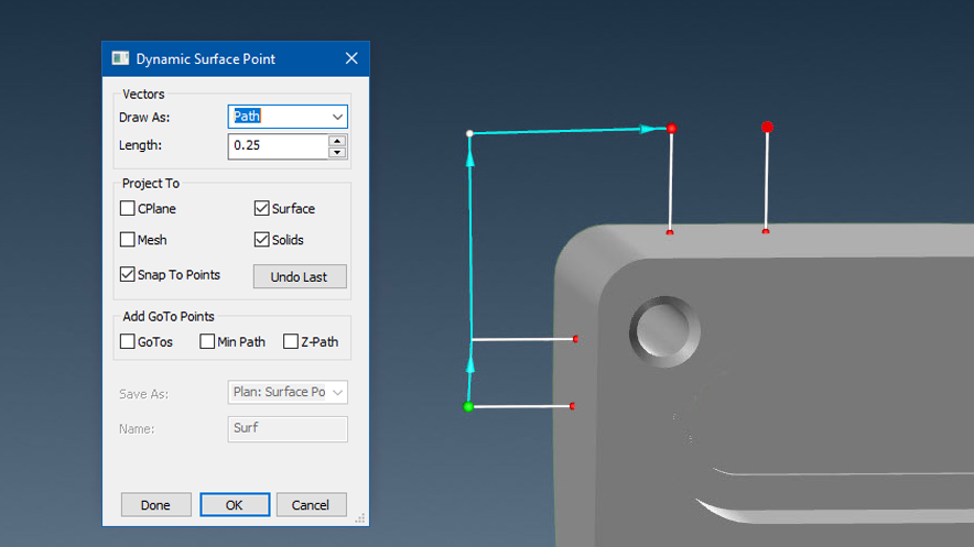
This function allows the operator to place points on a surface using the mouse to indicate the location and then use a left mouse click.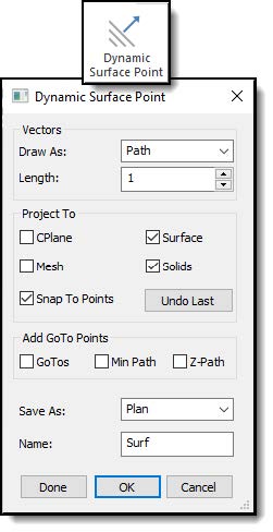
Vectors Control
- Draw As – choose from four options:
- Vectors – displays vector of Surface Grid points, Length value, controls the length of the Vector.
- Probe – displays a probe when creating the Surface Grid.
- Target – displays Targets when creating the Surface Grid.
- Spheres – displays Spheres when creating the Surface Grid.
- Length – when selected, the normal surface vector displays, and the vector’s length may be modified. You may change the Vector direction by clicking the Vector button and use it for CMM Programming as the minimum clearance setting.
Project To:
- CPlane – surface points created on surfaces that lie on the active CPlane.
- Surface – creates surface points on active Surface entities only.
- Mesh – creates surface points on active Mesh entities only.
- Solids – creates surface points on active Solid entities only.
- Snap to Points – creates a CAD point on a surface and snaps to the point positions. Ideal when needing defined surface point locations.
- Undo Last – removes the last defined Surface Point.
Add GoTo Points – only active when selecting Plan for Save As.
- GoTos – activates collision detection for CMM automation and adds a Goto point for moving the CMM Probe around the part.
- Min Path – used for CMM Programming; when activated moves, the Goto points up and over the part when minimizing the path distance.
- When activated, Z-Path – used for CMM Programming, moves the Goto Points up the Z-axis of the active WCS to the highest clearance plane. Use the Length control as the minimum clearance setting for the probe as it moves around the part.
Save As – from the drop-down (below), select the type of result to save:
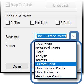
- CAD Points – saves to active CAD Level.
- Measured Points – saves to the Verisurf Data Tree under the Points node.
- Cloud – saves to the Verisurf Data Tree under the Cloud node.
- Analysis – as an Analysis object in the Verisurf Data Tree under the Analysis node.
- Targets – saves as an Auto Align Target in the Verisurf Data Tree under the Targets node.
- Surface Point – as a single point Analysis object in the Verisurf Data Tree under the Analysis node. Ideal when calculating distances.
- Plan: Points – creates a Plan (or adds to an existing Plan) with Surface Points.
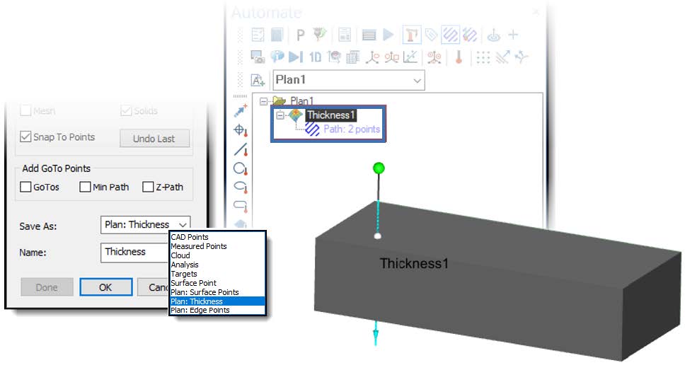
- Plan: Thickness – creates a two-point Analysis object to inspect the Thickness of an object.
Feature Name – enter a name and number for each point.
Done – ends current selection, leaves the dialog box open.
OK – ends selection and closes the dialog.
Cancel – removes all selected points and closes the dialog.
Dynamic Surface Point Thickness Feature
By selecting Save As Plan: Thickness in the Dynamic Surface Point dialog, a two-point Analysis object is placed in the Plan; this is a quick method of measuring the thickness of a part.
- CMM Plan one-click part thickness
- Automatic GoTo’s & collision avoidance
- Works for manual devices & scanners too
Dynamic Edge Points Feature
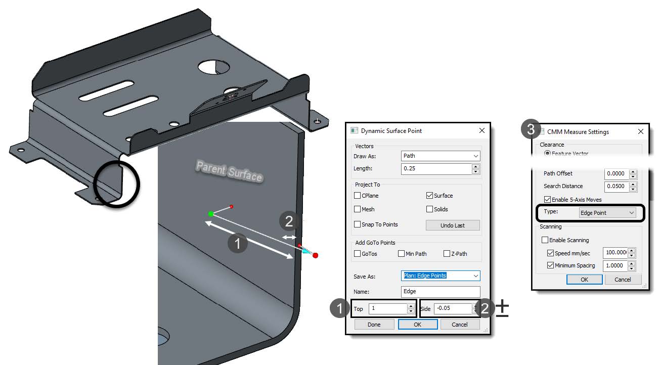
Verisurf simplifies CMM inspection of “trim” or EOP – edge of part, on thin sheet-type parts with contours that vary from nominal form. Dynamic Edge Point adapts the position of the edge measurement based on the profile variation of the parent surface. This ensures a valid measurement is taken on the edge surface and doesn’t try to trigger a point that is off the part.
Dynamic Edge Points can be created interactively by selecting the top parent surface or snapped to discrete points on the model. GoTo Points can also be utilized to aid in collision avoidance.
- Top: controls the distance from the edge on the top surface. A rule of thumb is one to one and a half times the thickness of the material to minimize deformation.
- Side: controls the distance down the face of the edge. A rule of thumb is half the thickness of the material.
Note: Dynamic Edge Points supports all 3-axis and 5-axis probing systems.
Regardless of the probing system, the Type in the CMM Measure Settings (3) automatically sets to Edge Point. When in Edge Point, the first point is used to adjust the measurement location of the second point.