
How to Close the Loop on the
Digital Manufacturing Workflow
Get a PDF reprint of this story from Quality Magazine HERE
Get a PDF reprint of this story from CNC West Magazine HERE
By Ron Branch, Manufacturing Engineer, V & M Precision Machining and Grinding
(This article produced in collaboration with CNC West, April/May 2011)
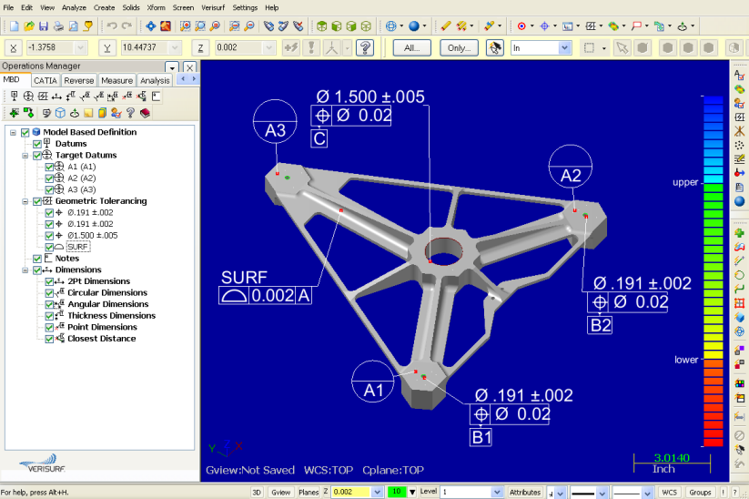
Verisurf X CAD-Based inspection software uses ASME Y14.5-2009 GD&T symbols as part of its CAD interface. CAD-based GD&T annotations can be imported as part of the CAD file if supported by the program, or added to the CAD model with Verisurf X.
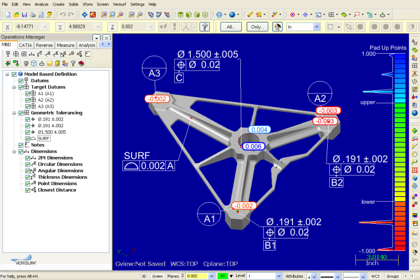
Verisurf X illustrates high and low tolerance deviations on associated CAD model GD&T specs.
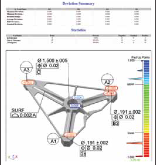
Verisurf X uses the CAD model as the nominal definition to generate custom reports in industry standard formats, including GD&T constraints and color deviation maps. A Database Write feature in the program formats and sends inspection information to SPC applications and PLM databases used by major manufacturers. The feature also supports Microsoft Access and SQL Server database formats for combining Verisurf inspection data with numerous enterprise databases.
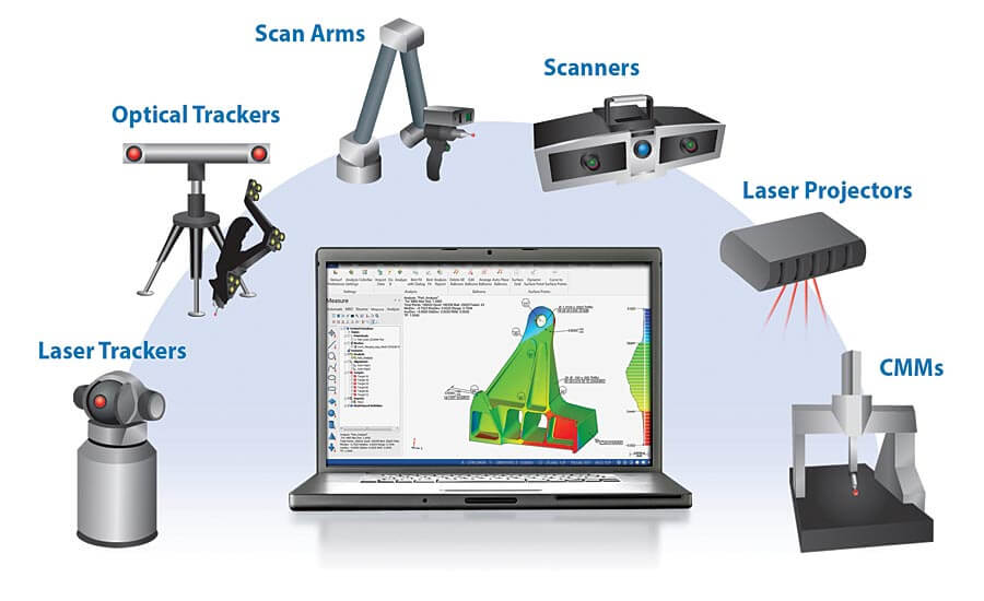
Verisurf X provides a common software platform to drive all digital metrology devices. Benefits include reduced training time across multiple devices, consistent reporting formats, and support for upstream enterprise databases.
Computer Aided Inspection (CAI) software helps CAD, GD&T (Geometric Dimensioning and Tolerancing datums), and measuring devices work together to ensure design intent, and eliminate the need for 2D inspection drawings while closing the loop on digital workflow. These are all important considerations when moving towards a Model-Based Definition (MBD) environment. CAD-Based inspection is a good first step toward achieving a complete MBD environment. The central concept of MBD is that a 3D CAD model provides all product information needed for all aspects of the product life cycle. Engineers have wanted to harness the power of MDB for years.
In a 2005 presentation, Terrence McGowan of Boeing, stated, “The 3D model should contain everything needed from design to manufacturing, in particular, GD&T.” What that means for manufacturing and inspection is that all dimensions and tolerances are pulled from the 3D CAD model, not from 2D drawings. Making the CAD model the authority removes the ambiguity, conflict, and doubt that arise when drawings and models co-exist. With authority bestowed on the CAD model, MBD eliminates errors that result from referencing an incorrect source and makes processes more efficient-no more searching to determine correct revision levels.
For the enterprise, the benefits are many and diverse. MBD is the single information source to build and maintain products, and it integrates into processes from cradle to grave, providing definitions for operations throughout the product lifecycle. Yet, to summarize MBD’s impact, one only has to look at the goals of leading aerospace companies when they began their pursuits of MBD. They wanted to improve quality, accelerate time-to-market, and decrease time and expense.
A common misconception is that MBD is synonymous with 3D CAD or GD&T datums. Some incorrectly believe that using GD&T on a CAD model is MBD. While GD&T is a necessary component of MBD, much more information is needed to have a true model-based definition. However, GD&T and CAD-based do move the CAD model from design to a manufacturing orientation. It opens the door to many advantages where software can automate and validate steps in the simulation, manufacturing and inspection processes.
GD&T is a Universal Language
A necessary component of CAD-based inspection and the MBD approach is GD&T, a universal symbolic and tolerancing language. Last updated in 2009, GD&T has been rigorously studied and applied by thousands of manufacturers around the world. It is often considered essential for communicating design intent – that is, that parts from technical drawings have the needed form, fit, function, and interchangeability. The recent update includes changes in feature design, datum references and degrees of freedom, surface boundaries and axis methods of interpretation, profile tolerances, the symbols and modifier tools.
In manufacturing, the direction of CAD is toward 3D. However not all CAD programs provide intelligent GD&T data. Here, intelligent means computer-readable, and, thereby capable of feeding downstream applications. There are two GD&T definition-data formats. Potentially confusing, both are labeled “3D annotation,” but one format is purely for display, while the other provides intelligence back to the CAD model.
The distinction is that in the display format, text is used to associate tolerancing to the model. In other words, humans must interpret the GD&T information, opening the door to potential errors. The display is similar to a math equation in Microsoft Word, which conveys information, but cannot be used in calculations. What makes the effort of applying GD&T to 3D models worthwhile? As part of the MBD approach, it helps users leverage data throughout product development, cutting time from processes and improving them while avoiding investment in 2D drawings. In effect, 3D GD&T data acts as a form of “artificial intelligence” for manufacturing and inspection.
3D Computer Aided Inspection
GD&T defines quality requirements, and inspection then confirms these requirements are being met. For CAD-based inspection to occur there must be GD&T representation and the inspection software must be able to import the data from the native CAD software. Or, when intelligent GD&T data is not available, users must be able to add it to the CAD model in the inspection software.
CAD-based inspection involves inspecting physical part measurements against the CAD model. This process can be dependent or independent of how or where tolerancing is defined on the CAD Model. Consider, for example, inspection software such as Verisurf X from Verisurf Software Inc., Anaheim, Calif. It connects to and controls measuring devices such as scanners and laser trackers, as well as stationary and portable coordinate measuring machines (CMMs). It also accommodates both presentation and intelligent GD&T specs from CAD models. Intelligent GD&T datums are imported directly from the native CAD software with the 3D model and provide nominal dimensions. For presentation annotations, the quality or manufacturing engineer uses Verisurf to add GD&T specifications to the 3D model. Importing information from a native CAD package as a 3D CAD model with GD&T representation is a good example of moving towards an MBD environment. The accuracy of the dataset is preserved. The same applies when GD&T display data (presentation) is imported directly (or via STEP translation) and entered into the inspection application. In both scenarios, there is no need to invest in creating or maintaining 2D drawings.
Open Inspection and Measurement Platform
It is important that CAD-based inspection software serves as a common platform and communicate openly with all CAD software and all metrology devices, across the manufacturing enterprise. For example, Verisurf X software can import all native CAD models; it also connects to and drives all digital measurement hardware devices, including CMMs, laser trackers, and scanners, and has open database architecture, which enables data sharing with downstream databases and applications.
Digital Workflow and the Model-Based Enterprise
CAD-based inspection truly closes the loop. It feeds back to the CAD data authority with little delay, making inspection results more valuable and easier to attain. It eliminates interpretation and ambiguity concerning the design intent and functional demands. CAD-based inspections provide feedback to simulation and tolerance analysis by providing insight to any deviations. Feedback goes to manufacturing engineering, which uses the data to determine root cause and devise plans to put processes under control. If that is not possible, design engineering receives feedback that allows it to revise dimensioning and tolerance specifications to make products work in those areas that are critical to function. It has long been said that you cannot improve what you cannot measure. CAD-based inspections foster improvement by making it feasible to measure more, measure faster, and measure better.
Model-Based Definition and GD&T
GD&T is used on engineering drawings and computer-generated CAD models to explicitly describe nominal geometry and allowable variations. Dimensioning specs (for example, a basic dimension) define nominal geometry. Tolerancing specs (for example, linear dimensions) define allowable variations for individual features and allowable variations in orientation and location between features. A closer look at 3D GD&T GD&T is used on engineering drawings and computer-generated CAD models to explicitly describe nominal geometry and allowable variations. Dimensioning specs (for example, a basic dimension) define nominal geometry. Tolerancing specs (for example, linear dimensions) define allowable variations for individual features and allowable variations in orientation and location between features. GD&T is defined in ASME YI4.41-2003 and ISO 16792:2006. 3D GD&T symbols include those for form, profile, orientation, location, and runout.
How To Perform Computer-Aided Inspection
Here are the steps to using CAD-based inspection software that includes GD&T, such as Verisurf X:
- Within the inspection software, open the 3D CAD model file of the part to be inspected
- If necessary, manually add GD&T specifications
- Using the software, develop a manual or automated inspection plan
- Run the inspection process. Verisurf X works with all digital metrology devices
- When using a PCMM, the software prompts operators to pick points that will align the physical object to the CAD model. For GD&T definitions, these alignment features are datum references. Once aligned, the software prompts operators to pick points on the part in the sequence determined by the inspection plan
- As measurements are taken, the software displays results graphically. Immediate feedback should show the value and deviation from the embedded GD&T tolerance.
Thus, operators know immediately if a feature passes or fails inspection.
Verisurf Software, Inc.
Verisurf Software, Inc. is an advanced three-dimensional measurement solutions company committed to delivering advanced computer-aided inspection and reverse engineering solutions. Verisurf software helps manufacturers of all sizes and industries produce higher quality products in less time and at a lower cost with automated, Model-Based Inspection processes. For more information, visit the Verisurf website at https://verisurf.com.