
The FARO Arm with Verisurf Software
The FARO arm portable coordinate measuring machine (PCMM) is a measurement device that has provided reliable and essential service to manufacturers all over the world for decades. Likewise, Verisurf software has long been the software prolifically matched with FARO arms everywhere to allow them to perform at their highest efficiency and ease of use. These FARO-Verisurf systems have become integral to many QC, Production, and Engineering organizations. They are relied upon for the important tasks of in-process, first article, and final inspection for a variety of dimensional, alignment, and contour verifications. They are also valued as the primary tool for reverse engineering (RE). For RE, Engineers use the combined system for both as-built and design-intent purposes. The task is to produce 3D design models for engineering, manufacturing, and collaborating with vendors and customers. With Verisurf being a true CAD-based software platform, it gives the FARO arm extra compatibility with any of the several design systems used by manufacturers.
For FARO arms that have been bought with simple, basic software systems, they are often underutilized to their fullest potential. Many organizations choose Verisurf for their FARO arm upfront as their software of choice with the system. For those who do not, and later switch to Verisurf, they typically find themselves using the arm more often and even follow with the purchase of more FARO arms having seen the true value of a high-functioning system. Verisurf is designed with the user and their unique challenging tasks in mind.
The Basics of the FARO Arm
Developed by a company founded by Simon Raab and Greg Fraser in 1981, this very versatile device, capable of measuring what would otherwise be difficult if not impossible to access. It is a portable device able to measure anything-anywhere and has a track record of solving problems. It often replaces processes and devices that formerly took much more time and money, and it modernizes organizations with reliable and flexible processes to meet any challenge. As with all CMM-type devices, it can measure contours that are not able to be inspected (size and shape, for example) by typical hand tools such as calipers, micrometers, rulers, and height gages. And for part features that can be measured by traditional hand tools, the arm allows use of the CAD model as the nominal (the as-designed part dimensions and shape), which speeds the inspection process and eliminates transposition errors that are frequent with non-digital methods.
The Basics of Verisurf Software
Verisurf software is a true, CAD-based platform. It is designed by users, for users, elevating all CMM-type devices making them more efficient and easier to learn. It makes them take less time to set up an inspection, to perform the inspection, and to finish the inspection report. It has a vast functionality toolkit that will not leave its users left out in the cold. Verisurf gives the user functionality to complete tasks with fewer mouse clicks and button-pushes. It does not burden the user with “wizards” or things that slow you down, but at the same time has very powerful automation capabilities so you can create user-prompted inspection plans which control the whole process. Therefore, it has the best of all worlds with on-the-fly measuring that requires zero setups, “teach mode” that automatically creates an inspection plan from the earlier measuring or programming from CAD which can be set up without the need of the device for which it is intended.
Verisurf software adds these same productivity enhancements to all CMM-type 3D measuring devices, including virtually all OEM brands of portable measuring arms, laser trackers, scanners, stationary-programmable and manual CMMs, and photogrammetry. The software was one of the first “3rd party” solutions that allowed customers to employ a single software across all CMM devices throughout their company. Implementation of common software across the board has many benefits that include reduced training and support costs, productivity and process control enhancements, and personnel flexibility.
3D Measurement Metrology Helps Fill the Expertise Gap
The time and experience needed to take complex measurements with “old school” hand measurement gages and dial indicators is an art form that has benefited from the great talents of those who have been using them for years. With the challenges that face employers in replacing those artisans, modern 3D metrology systems help fill the gap. It can take a long time just to set up a parallelism or concentricity measurement with tools such as V-blocks, dial indicators, and height gages. The training and experience as well as the finesse necessary to get good data is the purview of technicians who have been doing it a long time. With micrometers and calipers, you can see the gage readings wavering as your grip changes on the gage, and it is easy to see how different people will get different readings. Those readings must be written down as they are not automatically recorded by a digital system. With a FARO-Verisurf system, the operator simply takes feature measurements as prompted by the software. A precise measurement will be automatically recorded with no possibility of transposition errors.
The Synergized Paring of Ideal Hardware and Software
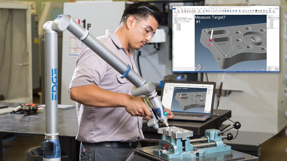
The whole is greater than the sum of its parts. The FARO arm-Verisurf combo brings together two efficiency-building solutions into one. With the arm and its multiple, unlimited-turn rotating joints, operators have easy access to measure features without the need to re-qualify or calibrate multiple probe angles as you would on a stationary CMM. You also cut the need for multiple setups and special holding fixtures, so it’s fast, convenient, and money-saving. With Verisurf software, you eliminate “Can it do this…?” limitations while at the same time, reducing the number of steps it takes to obtain measurements. The arm-software setup can even be programmed like a CNC CMM so that the user is prompted and stepped through a fully controlled inspection routine. Together this arm and software pairing creates a system that moves jobs along faster. And the skills needed to operate the system do not require extensive time in training and weeks or years of experience to be proficient. One customer noted, “it took my programmable CMM breaking down and trying out the FARO arm with Verisurf to finally eliminate the backlog in my CMM department.”
Process Control Enhanced by Software Automation
The non-motorized FARO arm, though it is a manual device, can be automated by software automation. The entire inspection can easily be created as a user-prompted plan that is saved as part of the CAD model, then can be executed at any time. It would be replayed on each part or sampling through the production run, prompting the operator through the inspection, controlling it to ensure it is done correctly, and making it fast and repeatable from part to part. The process has many benefits including ensuring the engineered datum schemes are employed and that no measurement gets missed, and no unnecessary measurements are taken that waste time. Verisurf software has many clever features that employ built-in advantages of the 3D model and CAD. A FARO-Verisurf operated inspection plan can take less time than a motorized measuring machine. This method provides extra process control, a favorite amongst QA managers and customer auditors. When your regular FARO-Verisurf operator is on vacation, others can inspect parts by simply hitting the “run” button and following the onscreen prompts.
Enabling Model-Based Definition (MBD) – the Digital Thread – the Connected Enterprise
MBD involves a digital 3D model as the controlling authority for what makes a good part. With MBD as the enterprise operating protocol, it helps ensure process control, consistency, reliability, and accountability throughout. The FARO-Verisurf system can be implemented plant-wide, on the shop floor, beyond the metrology lab. It can even go on the road to a vendor or customer. It has the benefit of virtually ending disagreements between the manufacturing and quality control departments. Monitoring of the digital end-to-end system is easily achieved and available to everyone from management through shipping.
Reverse Engineering – Part Digitizing
In addition to inspection, Verisurf and the FARO arm provide a great combination for reverse engineering (aka, digitizing) parts and assemblies. There are two primary purposes for reverse engineering: 1) Design intent – creating a 3D model of an undocumented part for manufacturing, 3D printing, engineering, etc. This involves normalizing measured features to design intent such as hole diameters, distance from the edge of the part, parallelism, perpendicularity, draft angle, etc. and 2) As-built – capturing the size and shape of the manufacturing part, which deviates from the CAD final part design due to intentional excess material or unintentional variation from warpage, spring back, etc. Examples of typical parts in this category include castings, forgings, molded parts, etc. This application is needed so that manufacturing and engineering can tweak downstream processes or adjoining parts of the assembly. In both cases, the FARO arm with Verisurf makes quick and accurate work of the job.
Scanning + Probing – The Combined Solution
The system, built upon Verisurf software, has a strong foundation with extensive capabilities for the hybrid use of the scanning-plus-probing solution. Especially for contours such as airfoils and automotive body panels, stamped sheet metal, molded plastics, and composites, the FARO arm scanner provides quick work with fine detail of the part’s external shape. Looking at the two different purposes:
Reverse Engineering
For reverse engineering, Verisurf adds easy meshing, NURBS surface creating and editing, with complete parametric solid modeling. To do this well, you need a comprehensive toolset, and Verisurf has all the tools plus an intuitive workflow. For basic primitive shapes such as holes, planar features, slots, etc., the scanner may be used or the operator may switch to the probe, especially for high accuracy measurement of deep features beyond the scanner line-of-sight. With Verisurf, its simple, straightforward measurement followed by export to CAD for as-built, or normalizing to design intent if that is the use-case.
Inspection
For inspection, the user might prefer the probe for alignment to hard datums and primitive features such as designated datum surface targets, holes and slots, then switch to the scanner for capturing every millimeter of the part. Good examples of this application are stamped or formed sheet metal and molded plastic or composite parts. Engineers want to know the results of the manufacturing process and clarify whether every radius is fully formed and to assess whether fine details are preserved from the manufacturing technique. Once again, the probe might be chosen to measure higher accuracy especially in holes, slots, and edge-of-part trim.
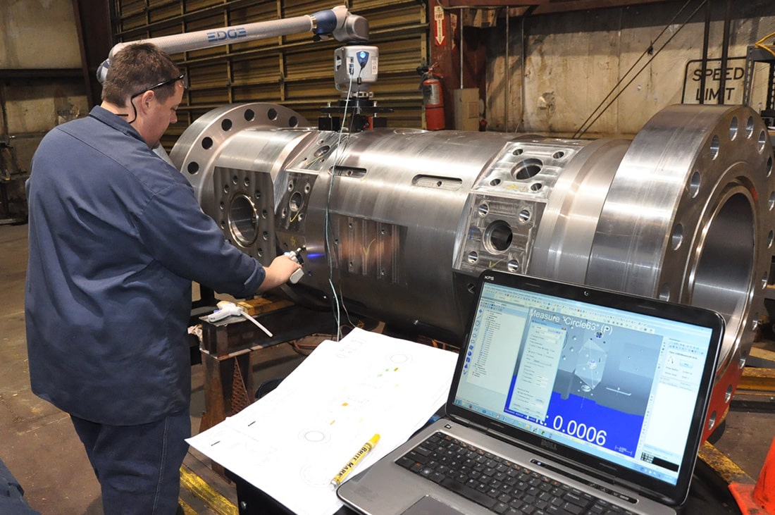
Measuring Large Parts or Assemblies with a FARO Arm
The largest volume covered by the largest FARO arm in production is the 4.0 meter arm. This measurement volume is not the limitation of the largest part it can measure. The arm can quickly and easily be relocated with special, Verisurf software-aided “leapfrogging” of the arm. This very simple step involves measuring what can be reached from location #1 of the arm, affixing a few targets that can be reached from location #1 and location #2, the targets secured typically with magnets or hot glue, measuring those 3 or more targets, then moving the arm to location #2, then re-measuring those same targets. This is all done as prompted by the software, and can be done in just a minute with little effort.
 Techniques to Better Measuring with a FARO Arm
New users of a FARO arm with Verisurf software quickly become proficient in productive use of the system. However, there are times when new users simply do not wish to depart from the old ways they have always measured things. And there are numerous cases when customers of the measuring arm purchased a less than ideal software package that frustrated the users. But when implemented with the right choice of arm and options, plus a decent plan for success, it typically evokes a feeling of “how did we live without this before?” Following are a few tips on technique with one section on probing and the other on scanning:
Probing – A few tips on handling the arm and if chosen, the scanner as well, can go a long way towards success. Handling the arm with one hand is often done and is certainly possible, and it is unlikely that anyone advises against it. However, you will probably find that it is easier to handle, to avoid fatigue, and to avoid the need to re-measure if you use two hands on the arm. When measuring small details that require extra precision, it may be helpful to use one of your hands and place your fingertips on the styli to gently hold it against the part while pressing the trigger to record points (measurements). This is not required nor is it always even a good idea, but there are times it may help. There is a feature within the software to switch from single-point mode to a scanning-type mode with the hard probe, sometimes called “drag mode,” and in Verisurf software the feature is “Continuous” mode. It allows the operator to acquire a fast stream of measurement points while “scrubbing” the surface of the part quickly. A feature of Verisurf that is particularly useful for scanning with the hard probe or LLP scanner, is “Filter.” The point Filter is very powerful in Verisurf, and has many options that allow the user to get a clean set of useful data. And with Verisurf, the filter can be used either while collecting a point cloud or can be applied afterwards. Remember to always check the probe calibration before an inspection. It is a good habit to adopt. Also, purchase of a certified length standard to check the arm accuracy from time to time is best-practice.
Scanning – Getting a good quality scan requires a little more training and practice. A few key tips are: 1) Make sure the scanner is calibrated, if not, calibrate it, 2) read the manufacturer’s recommendations for standoff distance and scan angle (best to be tangent and about 5-7 inches away from the part while scanning), 3) if not getting a solid distribution of scan data seen on screen while scanning, check to see if there is a surface reflectivity issue (if the part is shiny, black, or has transparency, it may require spraying the part with a dulling spray or setting the focus on the camera), 4) adjust your scan speed, the rate that you move the scanner across the part, to get a good solid scan (too fast can leave voids), 5) lighting in the room may cause a problem, so you may need to try turning off or dimming lights or close the blinds, 6) remember the scanner is line-of-site so it cannot see around corners nor deep into holes; sometimes it is a good idea to turn the scanner 90 degrees and see if you can capture missing data from your scan, 7) that being said, you should also try to minimize overlap of scans especially when reverse engineering is your task; it can make getting a good clean scan or mesh or surfaces difficult without doing a lot of dicey manipulation.
 What is a FARO arm?
A FARO arm is a portable coordinate measuring machine (PCMM). It’s a precision three-dimensional (3D) measuring device sometimes referred to as an “articulated arm” type of CMM. Its design starts from a base that includes a quick-mount that can be connected to a portable stand or cart via standard adapters used in metrology, but always has some type of base that can be secured via the aforementioned quick-mount or clamps, bolts, magnets or suction fixture that allows the arm to be securely mounted and isolated from movement during its use. The base includes system electronics control, connections for power and USB communications, battery and WiFi for wireless use. Continuing up from its base are tubes that connect 6 or 7 articulated joints, each which includes a precision encoder that tracks the joint’s rotation/position. At “the business end” of the arm is a subassembly often called the “wrist,” which has a mount for changeable measuring probes and control buttons assembly. Many have options for adding a non-contact laser line scanner, switchable between it and the probe.
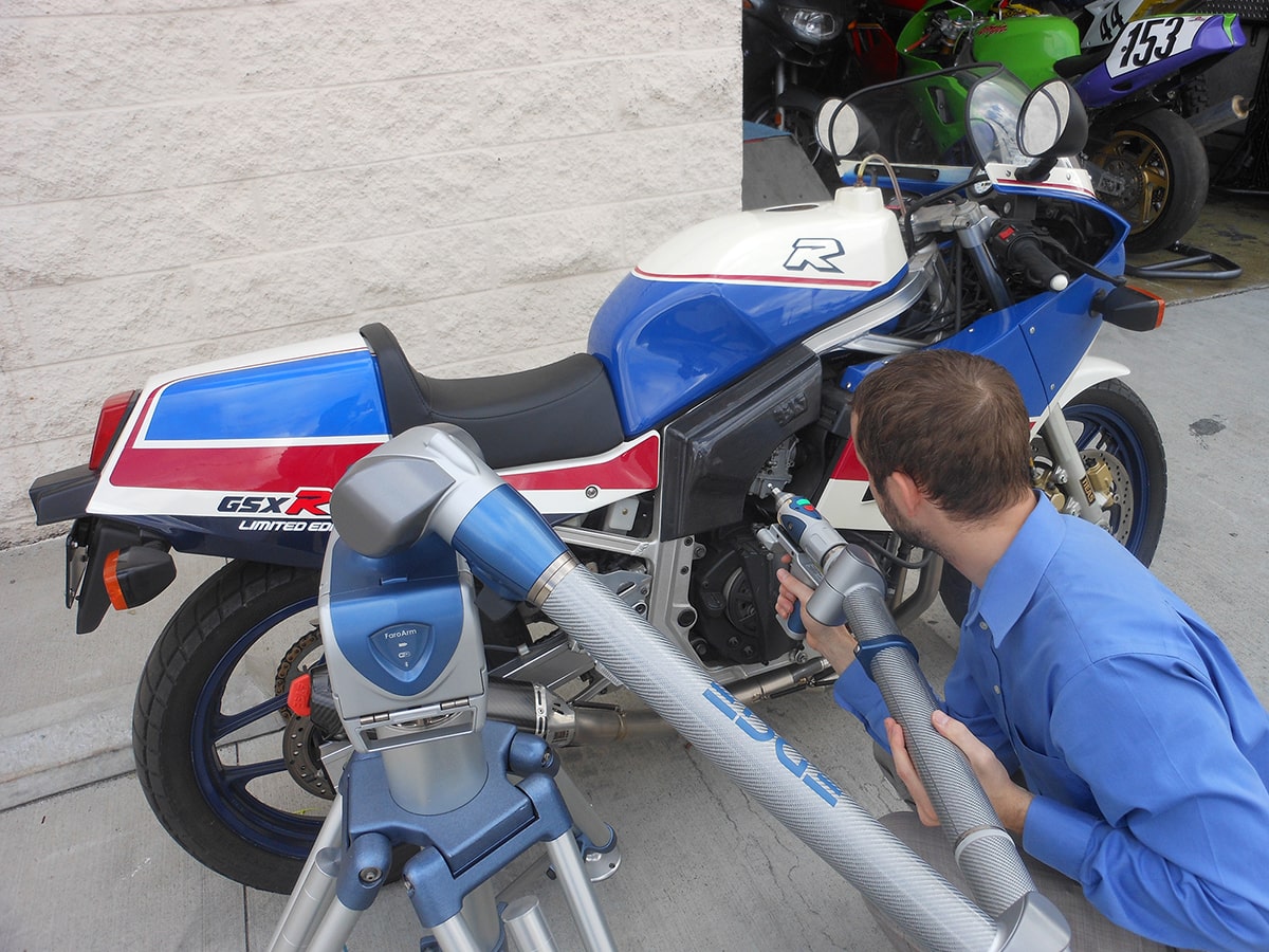
One can assume it was designed to perform the tasks of the earlier developed stationary CMM, a larger, precision measuring system designed to be “commissioned” in a fixed location in an environmentally controlled room. Unlike the fixed CMM, the FARO arm would be portable and make 3D measurement quick, easy and available anywhere. It could be used on the shop floor, anywhere in the plant, or even taken on the road for measurements out in the field at job sites, customers, suppliers, etc. Like stationary CMMs, the FARO arm is designed for computer-aided inspection (CAI). This opens up the scope of measurement capabilities considerably beyond that of 2D measurement instruments such as rulers, micrometers, and calipers. It is important to note that CAI also adds the ability to create automated program plans, and it allows utilization of the part or assembly’s computer-aided design (CAD) 3D model for the nominal, as-designed measurements.
Main Components of a FARO Arm
Mounting base – From the bottom of the arm is its mounting base. It has a metrology threaded ring that accepts the corresponding industry standard thread mount for fixing the arm to a variety of methods. Frequently used mounts that accept the arm’s threaded base are a fixed plate that can be clamped or bolted to a firm, stable structure such as a steel or granite table, portable cart, and others. There are also commonly used rolling stands of differing heights and functionality, vacuum and magnetic mounts.
Base module – Contains the arm’s main electronics, receptacles for 110/220 VAC power, USB communications, power switch, and data plate.
Encoders (either 6 or 7) – The arm has 6 rotating components, 2 at each of 3 joints, plus 1 extra just below the probe assembly on 7 axis versions. They have precision rotational scales that track the rotation position /angle, and each joint contains the mechanism that transfers power and data back to the arm’s control module. Each joint has the ability to rotate continuously without need of unwinding a hard-wired connection, making the arm more productive.
Tubes with integrated counterweight – Following the first set of encoders just above the base is the first tube. The arm’s tubes are of structural composite construction that makes it lightweight and promotes thermal stability. FARO arms are offered in different lengths so that customers can buy one that suits the size of parts they typically want to inspect. Lengths range from 1.2 meter volume to 4.0 meters volume. Therefore, the tubes are of different lengths to accommodate the different arm lengths that are offered. It is important to note that the shorter the arm, the more accurate they are. However, accuracy variation between the arm lengths is not significant but is enough that it should be considered when deciding which length to buy. Therefore, customers should buy the shortest arm that will measure most of their parts. Integrated within the tubes and arm structure is its counterweight. The feature (not visible externally) helps to take the weight off the arm so as not to fatigue the operator. This ergonomic design element also makes it easier to get accurate measurements by minimizing forces that might strain the operator while touching the probe to the part. Following the second set of encoders is another tube section.
Wrist – Next is the wrist, or short moving end segment of the arm. It houses a green button used for recording measurements, and a red button that can be programmed for a few different operations. It can be pressed to finish an operation, or to undo one.
Probe mount – A threaded metal mount accommodates the probe which is the business end of the arm. It allows easy changeout of probes of different configurations allowing for a firm seating of the probe so that it stays in place and is solid.
Probe and stylus – Last but not least is the measuring probe. The probe consists of the probe base and the stylus. It is designed to make it easy to quickly change from larger or smaller styli ball tips of an appropriate size to access and measure features that you need to measure. Most users have a handful of frequently used sizes of styli already threaded onto different probe bases so that it makes probe changes easier and faster. Styli tips consist of a shaft and ball tip that is usually ruby but can alternatively be ceramic, steel or other materials such as silicon nitride. There is a quick probe calibration procedure to be executed when making a change. The arm utility application runs the operator through a wizard to ensure a good calibration.
Optional laser scanner – A popular addition to the FARO arm is a FARO laser scanner (sometimes called the laser line probe or LLP). It is a non-contact assembly that is easily quick-mounted to the wrist for scanning a large volume of points, aka point cloud. The main components of this type of scanner is a laser line that is emitted from one aperture on the scan head, and a camera that interprets the laser beam as it bounces back at an angle from the surface of the scanned part. FARO offers three different versions of their laser scanner for the arm. The primary difference between them is the accuracy and field of view or speed of each. The scanner is a must for measuring soft parts that would otherwise deflect if touched with a hard contact probe. It is also the only way to go if doing highly detailed shapes, for example figurines, wood carvings, or sculptures to name just a few. But scanners are being used for a lot more these days. Stamped metal parts or formed plastic or composite parts are commonly scanned, as the manufacturers want to image every millimeter of the surface of those parts to see that the features and radii are fully formed. Scanners in combination with a hard probe is an excellent pairing since the scanner is line-of-site and also has limitations due to the angle between the laser and camera. In which case switching to the hard probe can usually do the job. It is common for users of “scan arms” to use the probe to measure holes, slots and datums and then switch to the scanner to record large amounts of data across the complete surface of the part.
What does a FARO arm cost?
Typically a FARO arm costs less than a stationary CMM, and can have a wide range of pricing based on options and size of the arm. New units without options start at approximately $25,000 and may go up to $60,000 for the largest probe-only systems. Arms with non-contact scanners start at around $35,000 and may go up to $100,000 for the largest arms with the highest end scanners.
Is a FARO arm considered a CMM?
Yes. It is a portable CMM. However, some industry individuals think of a CMM being a stationary, programmable, mechanized version of a CMM and put the Faro arm in the class of “articulated arms.”
What can a FARO arm measure?
It can measure part features such as holes, flats, slots, cylindrical or spherical elements, etc. For these “primitive” shapes it can measure size, variation from a mathematical-geometric calculated size, angle, and relationships to other features. More complex relationships between features can be measured and most often fall under industrial standards of GD&T, geometric dimensioning and tolerancing.
Possibly more significant is the arm’s ability to measure non-geometric primitive contoured shapes. These are “organic” shapes that are not definable by math geometric calculation, but still need to be checked to assure they are manufactured to the desired and necessary shape. Examples include body panels or stampings on cars, plastic covers for just about anything, airfoils on aircraft, inner flow paths for medical or fluids handling equipment, etc.
Conclusion
“Proof is in the pudding” as they say… So a live, onsite demonstration inspecting your parts to your requirements is the tell-all. It typically draws a response from first-timers like, “that took a lot less time and effort than it takes me now.” Verisurf Software, Inc. and FARO Technologies, Inc. team up regularly to bring the paired solution through implementation to success for their shared customers. You can provide your part, drawings, 3D models, etc. and they can demonstrate the workflow in your environment to your exacting specifications. You don’t have to make any commitment without assurance of the solution’s full efficacy.
Author: Scott Knoche – Verisurf Software, Inc. (technical marketing & sales at Verisurf since 2002)