Because at Verisurf, It’s About Time.
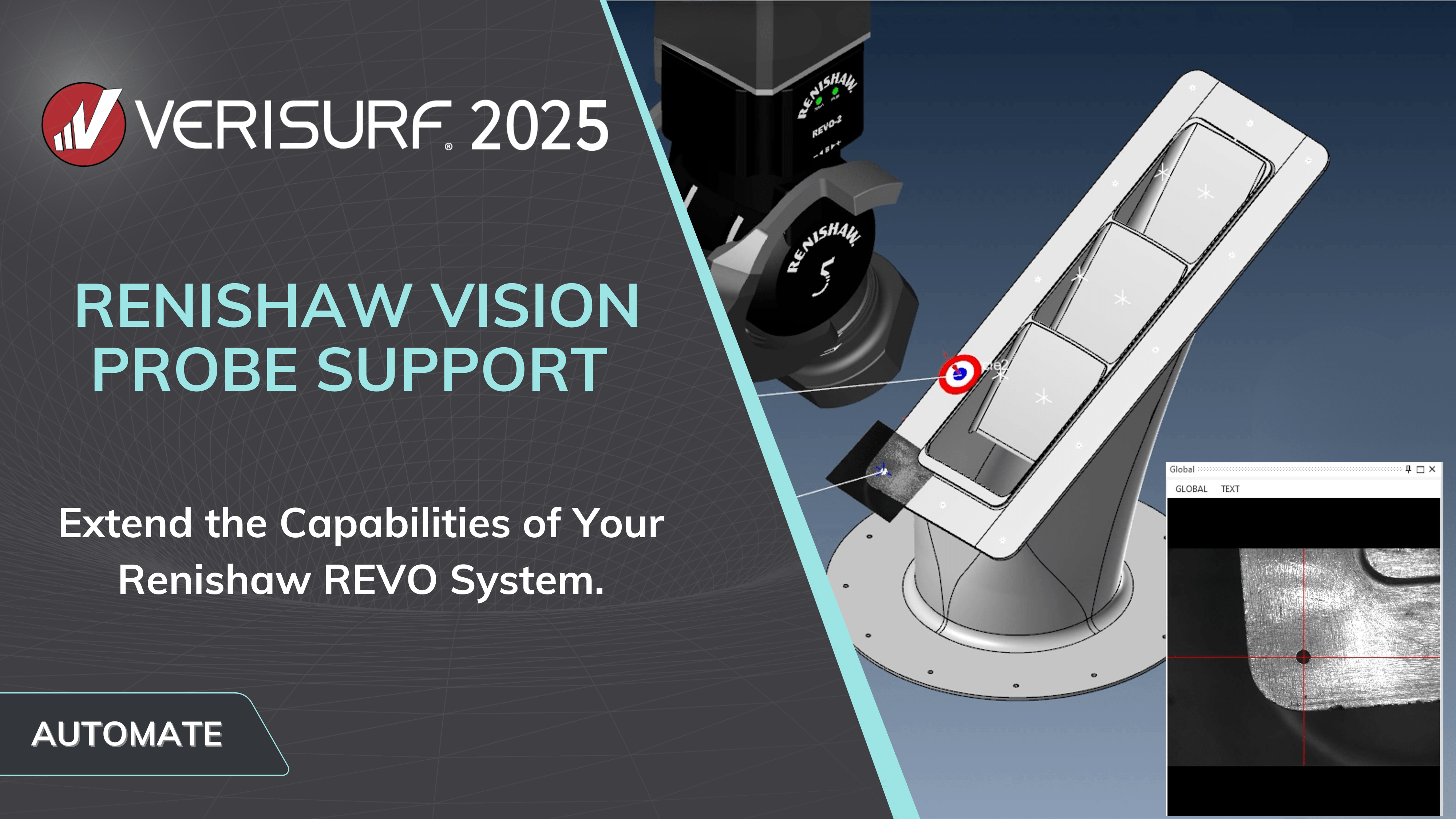
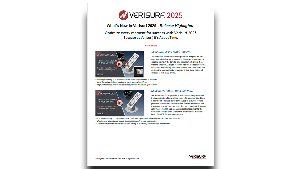
RENISHAW VISION PROBE SUPPORT
- 5-axis non-contact structured light measurement of complex surfaces
- Precise and aligned point clouds for inspection and reverse engineering
- Automatic exposure compensation for a variety of materials, colors and textures
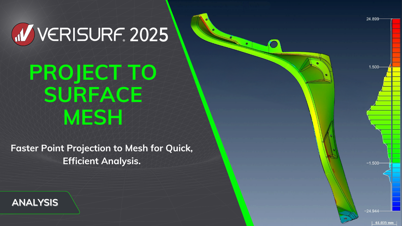
PROJECT TO SURFACE MESH
- Faster analysis through an option to project points to a mesh generated from surfaces.
- Cut the time it takes for profile analysis of complex shapes.
- Especially helpful for parts with a lot of surfaces and for large pointclouds.
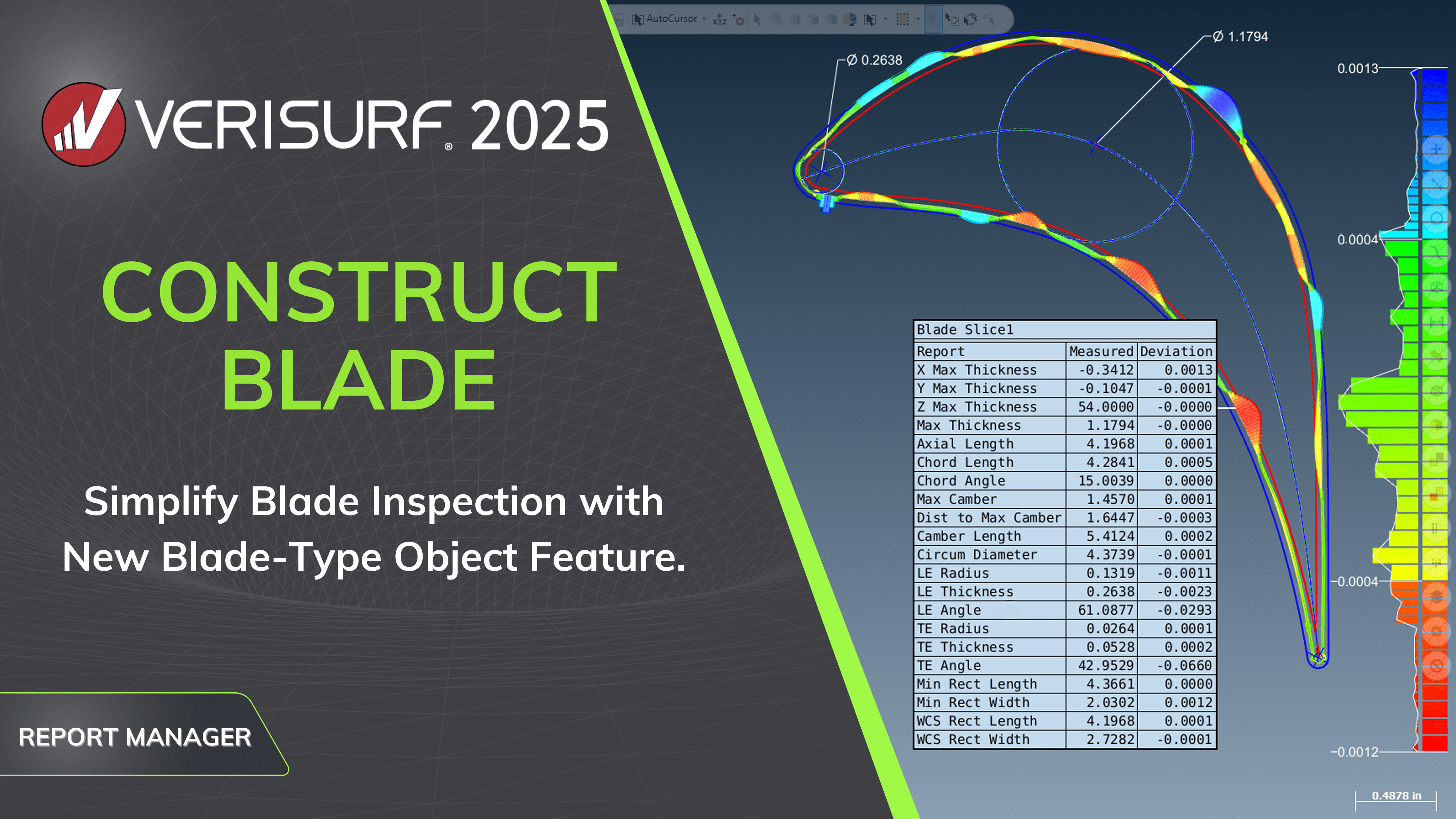
CONSTRUCT BLADE
- Profiles are analyzed to the model individually for reporting.
- Displays cross section results for the border, leading edge, trailing edge and maximum inscribed circles including camber-line; chord-line; and the centerline ribs.
- Report parameters including max thickness, chord length, camber length, max camber, leading edge and trailing edge thicknesses, radii, and angles.
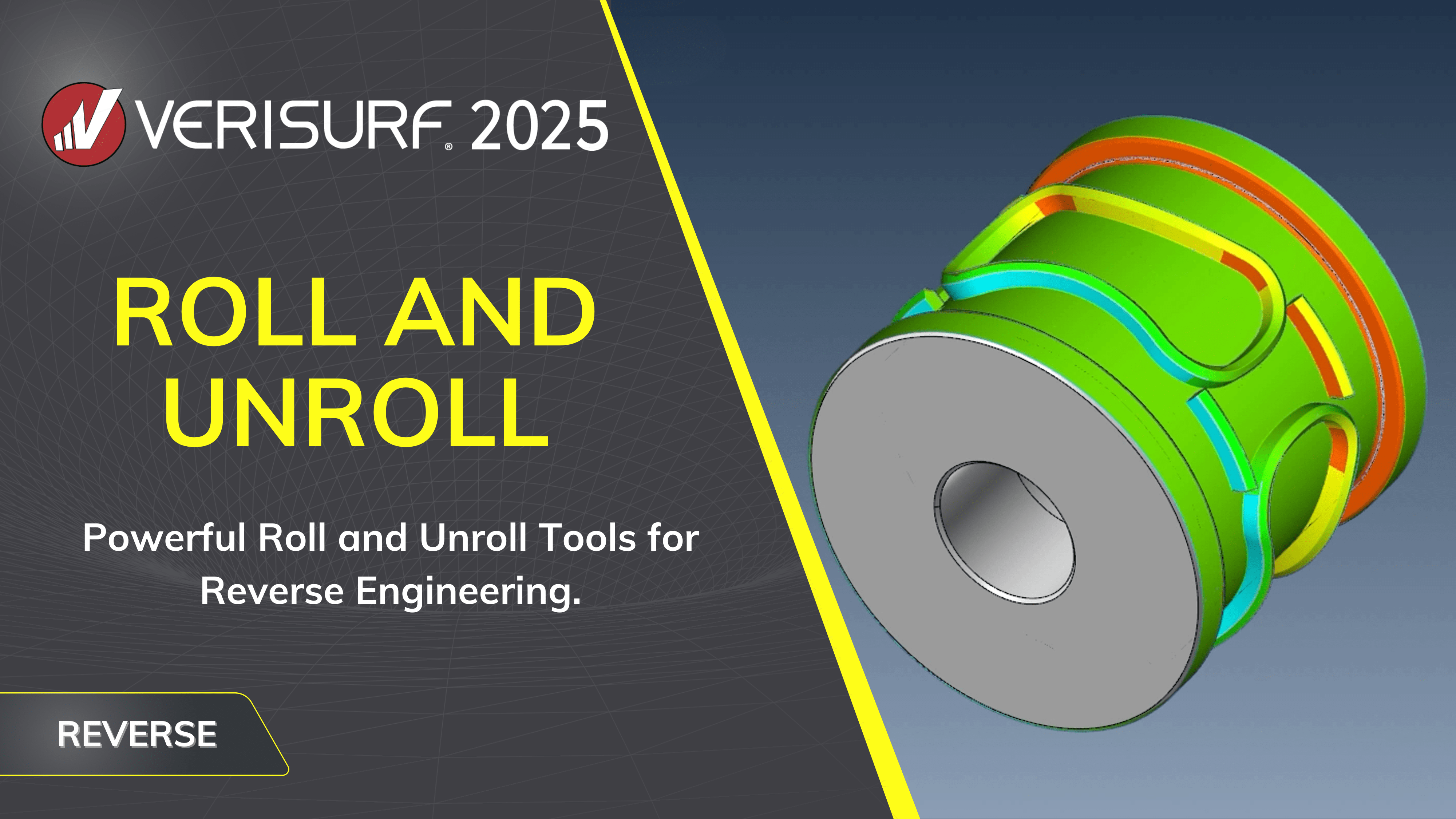
ROLL AND UNROLL
- Roll and Unroll works with all clouds and meshes, even those converted from CAD.
- Unrolling a scan facilitates part inspection, where the nominal values are provided from a 2D drawing, for example, which are designed flat and then rolled into shape.
- Scans with repeating and unique patterns can be unrolled.
- Scan data can also be rolled into a form that can be compared to a model of the working part.
LINE AND PLANE OFFSET
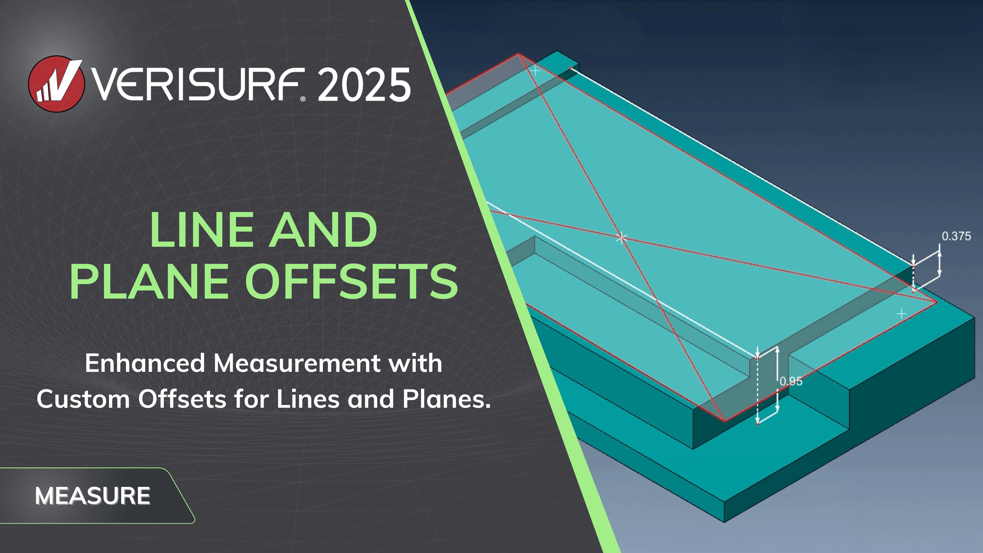
- Measurement of lines and planes now include use of custom offsets for calculated measurements.
- Used when a measured plane is defined by three points on two or more parallel surfaces that are offset from one another.
- When a 2-point line is measured on a stepped edge, the step value can be determined using a 2-point dimension and entered as the offset.
WAVINESS ANALYSIS
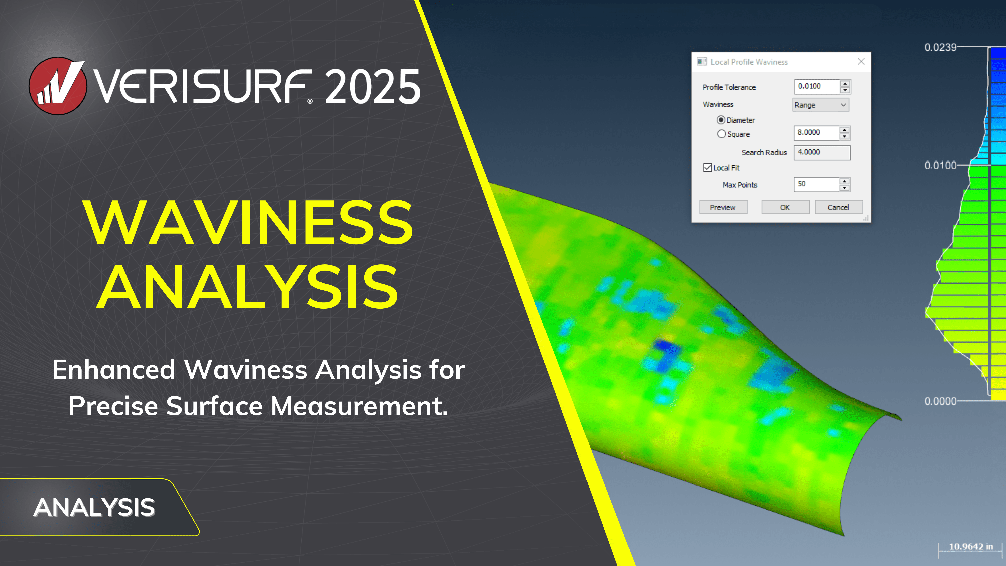
- Enhanced waviness analysis for clouds and meshes.
- Analyze range, average, and deviation based on a round or square sampling zone, applicable to both flat and contoured surfaces.
- Deviation Waviness helps identify the high and low areas on a part. This information is used both for reporting and for reworking a surface.
ENHANCED ACCESS TO EDIT MESH
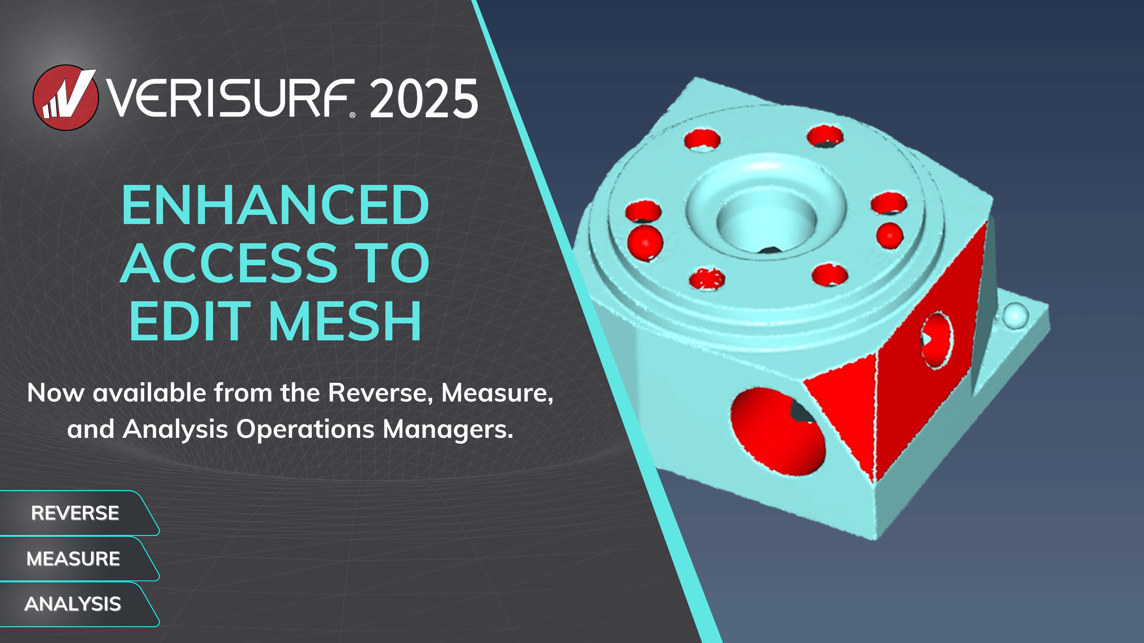
- Verisurf streamlines the use of mesh data by providing access to the Edit Mesh dialog from multiple operation managers, the Reverse, Measure, or Analysis Manager.
- Fast access to mesh editing is important with many new scanning devices outputting meshes.
- Both inspection and reverse engineering workflows require access to mesh editing tools.
INTELLIGENT PROBE ANGLE
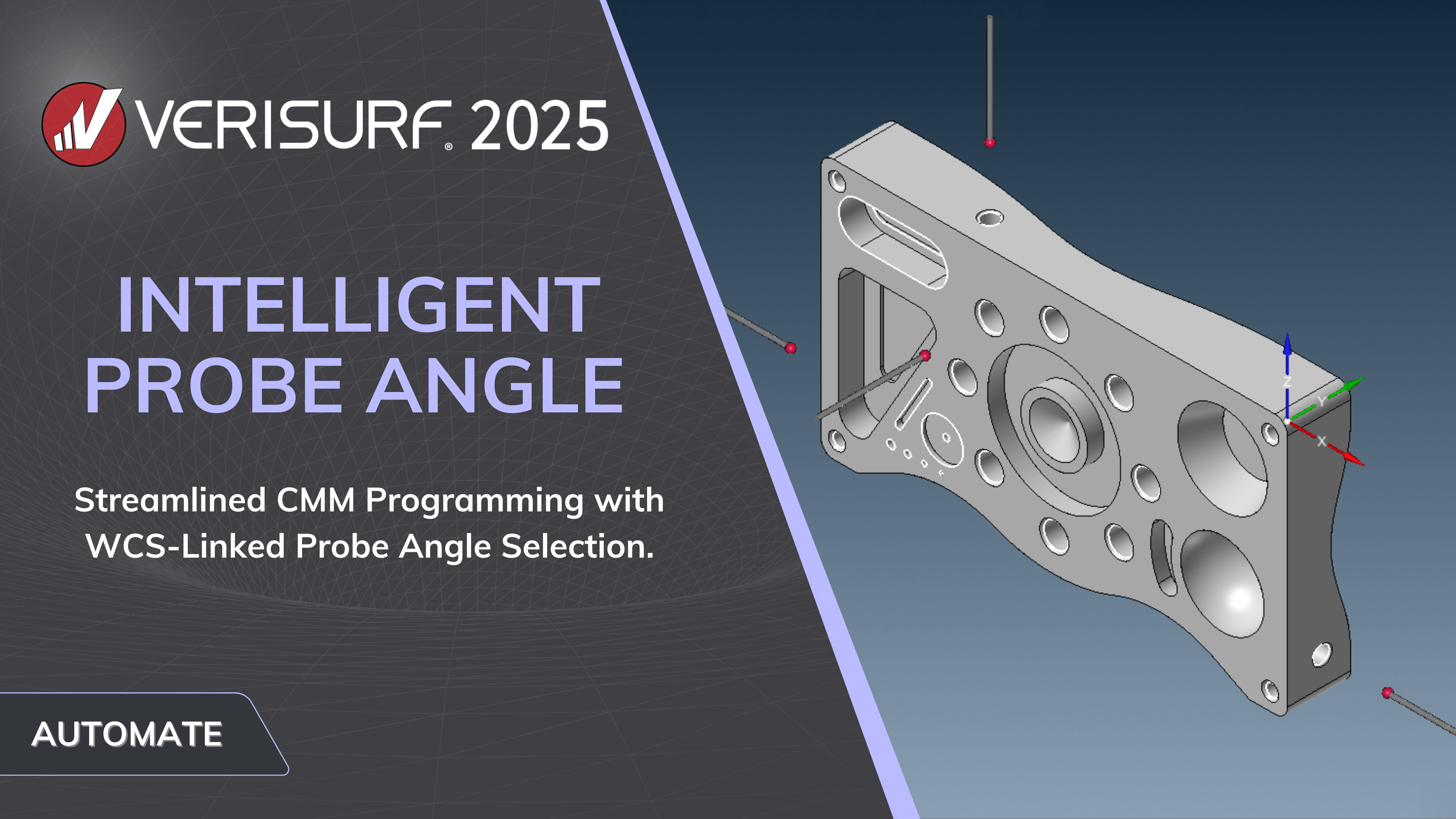
- For CMM programming the intelligent probe angle is associated with a Work Coordinate System (WCS).
- Changes to the WCS are reflected in intelligent probe angle.
- Simply select “Update WCS for Probes” to automatically set new probe angles based on the revised WCS.
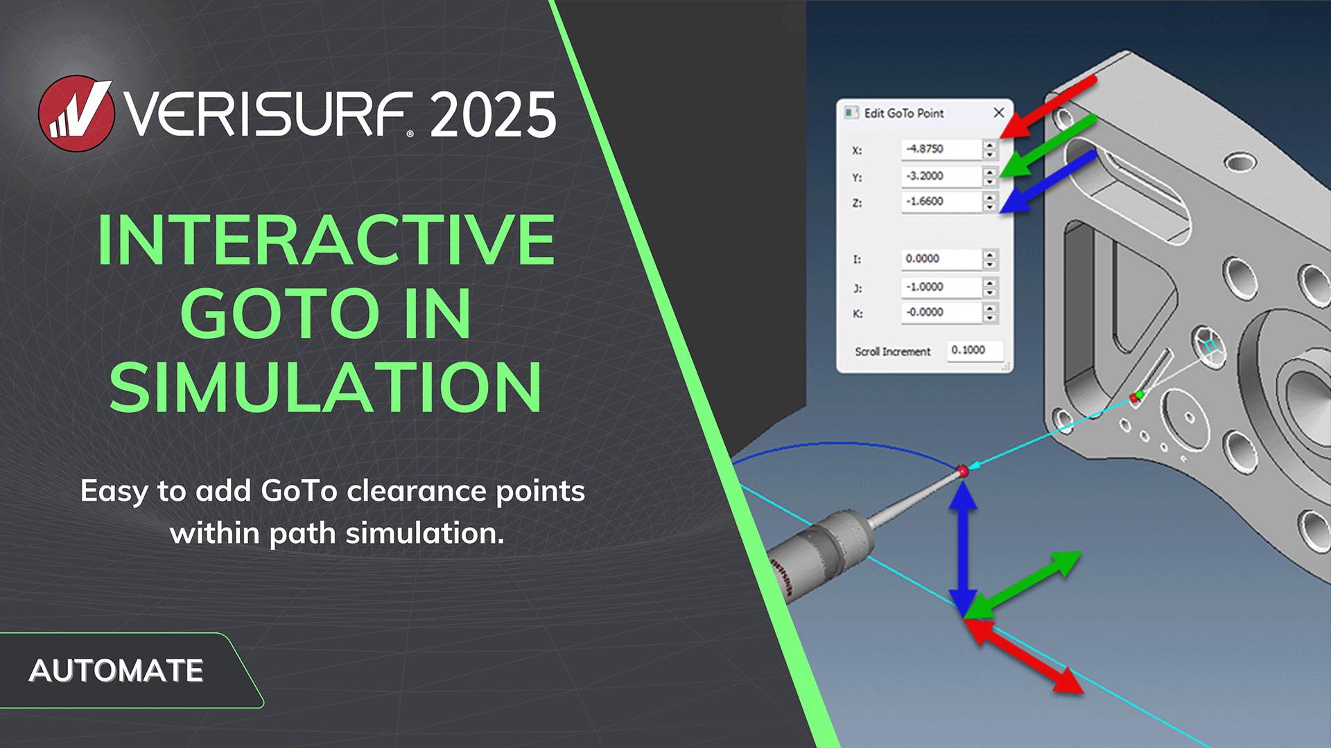
INTERACTIVE GOTO IN SIMULATION
- Easily add GoTo points interactively during CMM path simulation.
- In simulate mode, stop or drag the probe to the point before the indicated collision and simply scroll to a suitable GoTo location for clearance.
- When five axis moves are enabled, the vector of the Goto point can also be modified to ensure the correct approach to the feature.
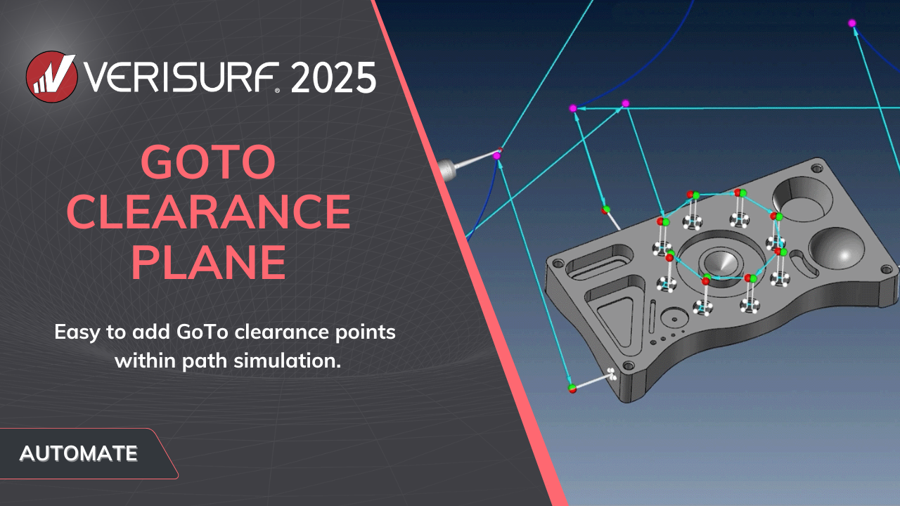
GOTO CLEARANCE PLANE
- The Clearance Plane option makes it easy to create Goto points in an inspection plan.
- Select the features above which to create a clearance plane, enter the distance above, and GoTo Points are automatically created at that level above the highest feature.
- Simulation confirms the new path clear of obstructions and probe movement as planned.
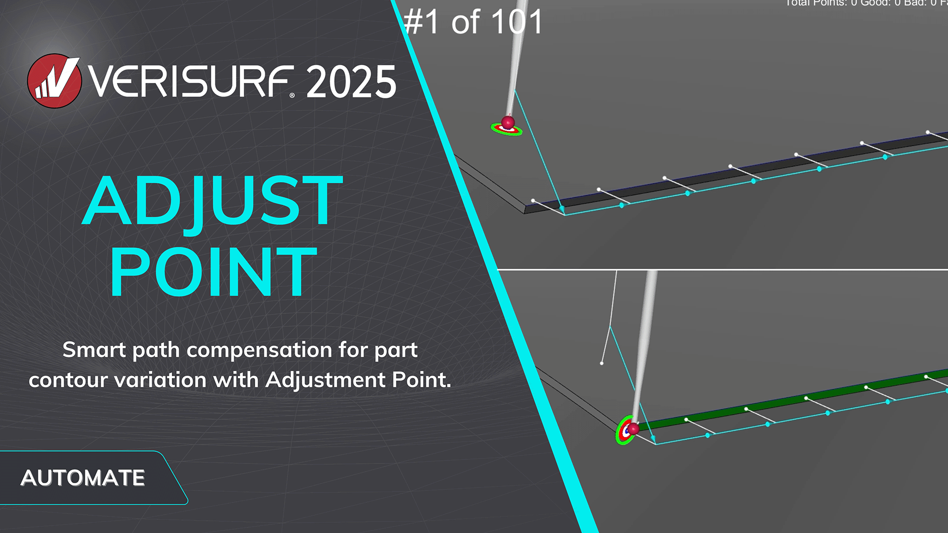
ADJUST POINT
- Simplifies the inspection of thin edges and shallow features through the addition of an adjustment point option for inspection paths.
- Adjustment points added to the probe path modify the locations of the nominal edge points to compensate for out of place edge surfaces.
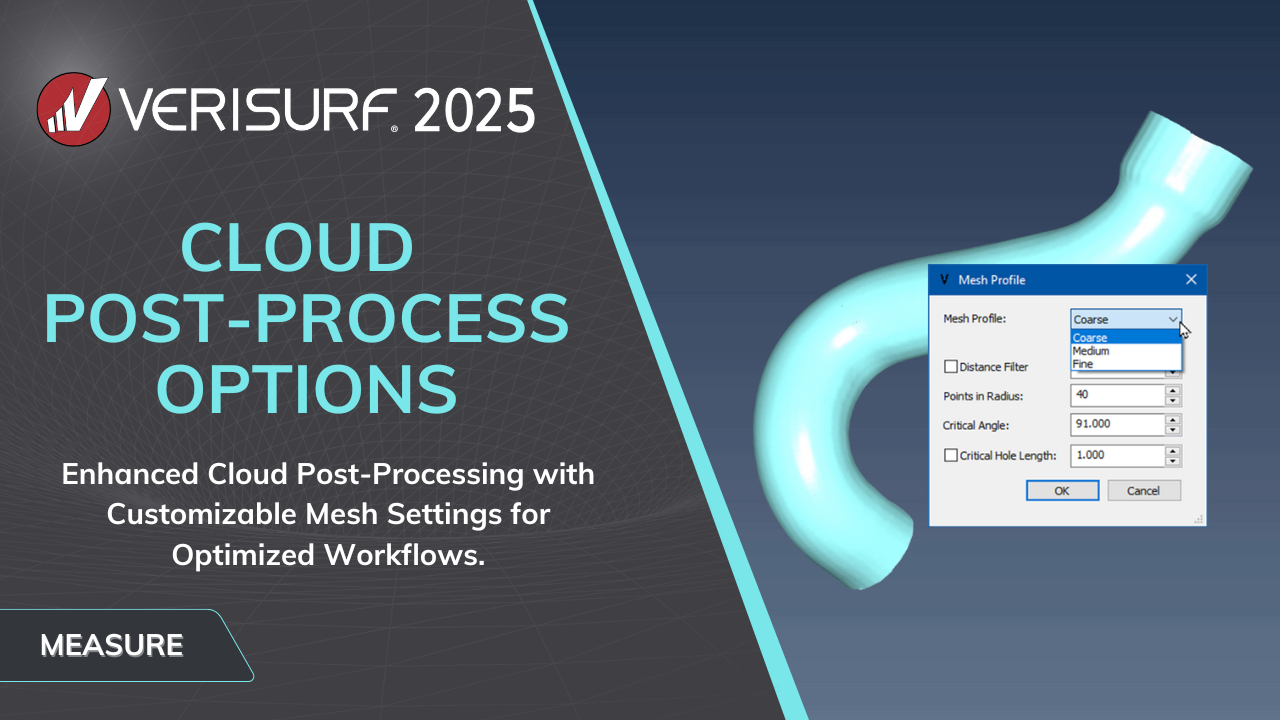
CLOUD POST-PROCESS OPTIONS
- New post-processing options for scanned clouds and mesh conversion for more efficient workflow and faster results.
- Options to select coarse, medium, or fine setting to optimize scanning of different types of parts.
- Quick, unified scan that emerges as a clean, single mesh right when scanning completes.
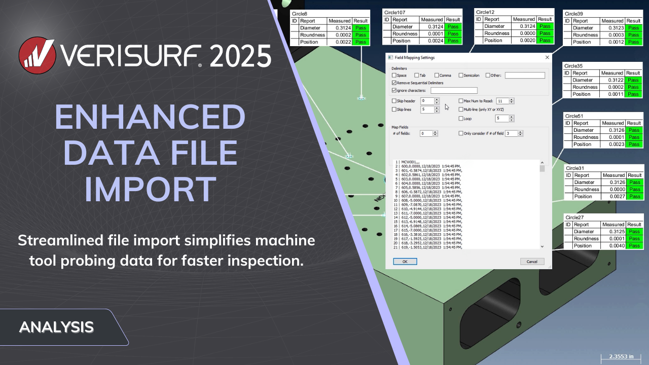
ENHANCED DATA FILE IMPORT
- Enhanced file import function provides additional support for machine tool probing data.
- Field mapping in the Data File import dialog provides a variety of new settings that simplify control of the data import.
- Parse data from virtually any machine tool probing system, allowing you to quickly inspect parts regardless of machine or software.
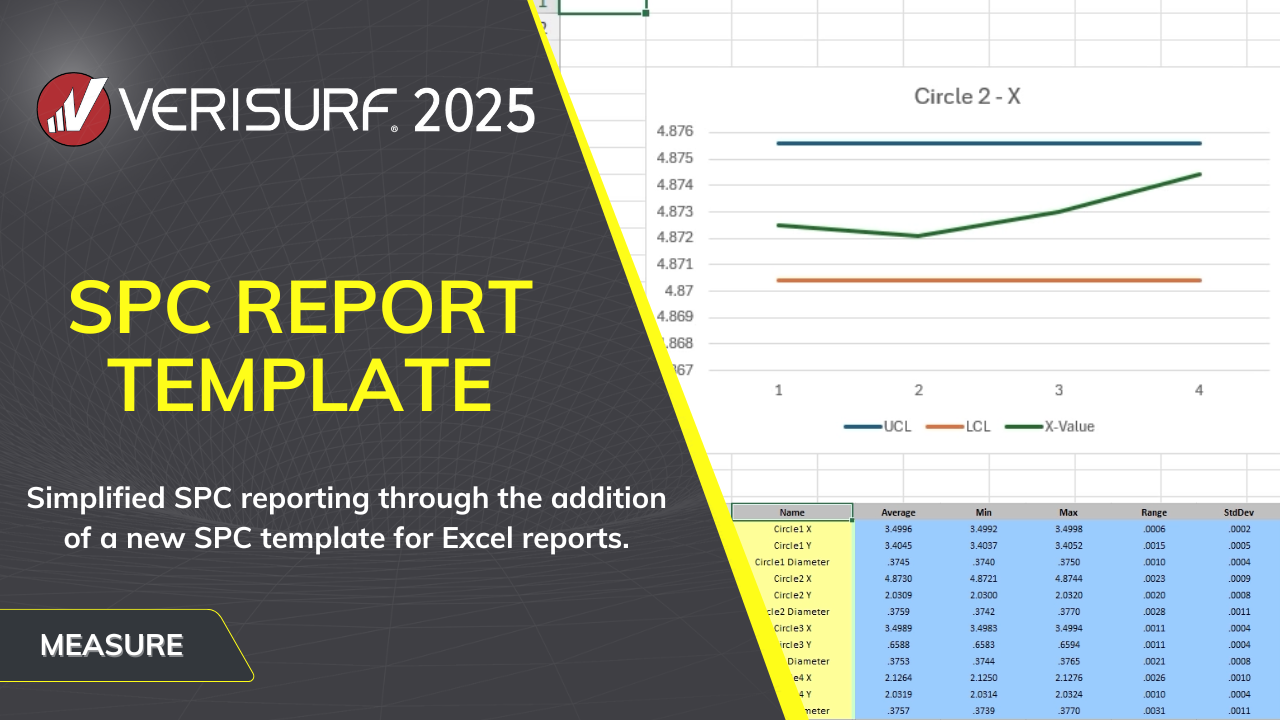
SPC REPORT TEMPLATE
- Simplifies SPC reporting through the addition of a new SPC template for Excel reports.
- Multiple part samples in a Verisurf data file can be added to a report, analyzed, and presented graphically.
- Display the average value and the upper and lower control limits of each characteristic, along with measured data, min, max range, and standard deviation.
INTRODUCING VERISURF 2025
In addition to the capabilities illustrated above, Verisurf 2025 includes more new functions and refinements to existing features. Contact us for a live or online demonstration or with your questions. Verisurf 2025 is another new release driven by our customers, partners, and professionals facing new measurement challenges in the real world.


