
Tech Tip – Create CAD Planes Perpendicular to
Splines, Arcs and Curves
Objective:
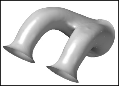
To place evenly spaced CAD planes perpendicular to a “drive curve” (lines, splines or arcs) that is created from a contour of a Port (Reverse Engineering of a “Port” is a common application). These planes that are perpendicular to the spline can then be used to measure 2D data (Measurement Settings – Filter – Surface Slice) to assist in developing loft curves when reverse engineering Ports.
While Ports are a common application, this methodology may also be used anytime measurements must be taken relative to any type of Mastercam Curve (Splines, Lines or Arcs). However, for this Technical Tip, we will focus on the Port Application.
Creating Planes Perpendicular to the Drive Curve
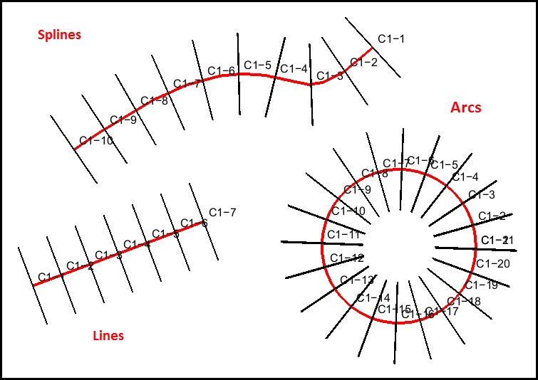
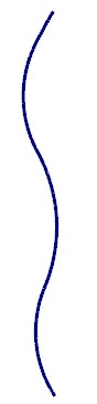
- For this Technical Tip we begin with a spline that can be created in a number of different ways; two examples:
-
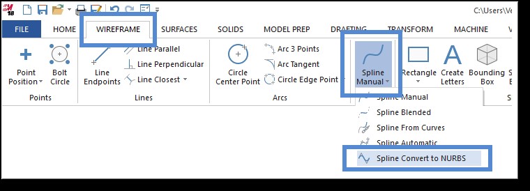
- A Spline may be measured in Verisurf and exported to CAD, the Splines must then be converted from parametric Splines to Nurb Splines in Mastercam using the Wireframe – Spline Manual – Convert NURBS function.
-
- Nurb Splines may also be created using Mastercam Wireframe – Spline Manual and then selecting one of the methods available.
- After creating a CAD Spline; from the Analysis Ribbon Bar menu select Verisurf Surface Points – Curve to Surface Points command to develop evenly spaced points.
- Using the mouse choose the spline/curve that you will be creating Planes on (must be in CAD).
-
- The Chaining dialog will appear, after you select your curves/spline(s) select OK in
the Chaining dialog.
- The Chaining dialog will appear, after you select your curves/spline(s) select OK in
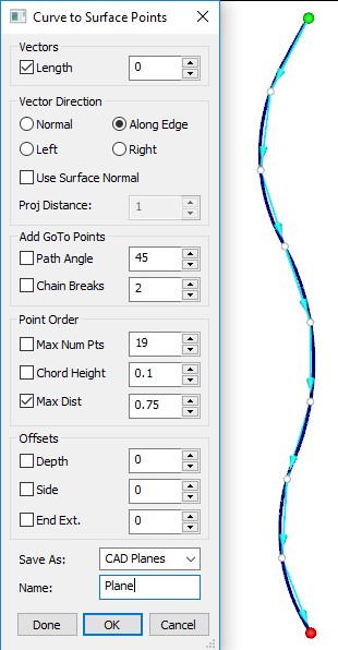
- The Curve to Points/Vector dialog will open (right).
-
- Length can be used to control the size of the created CAD Plane.
- Use Point Order control for choosing Max Distance (distance apart of points on Spline), Vector Direction (set to Along Edge) and choose to Save As: CAD Planes.
- Select OK when done, Planes will be constructed and saved on the Active CAD Level.
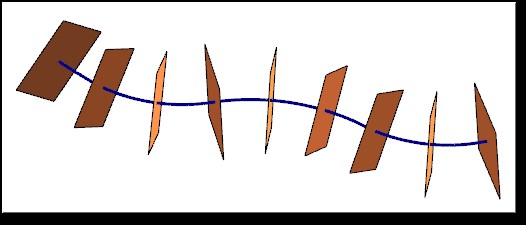
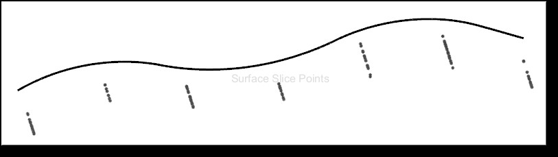
Measurement Results
In this case, after measurement you end up with Points placed perpendicular to your Drive Curve (Spline, Line or Arc) below is an example of pointclouds measured using Surface Slice. The planes that were used for Surface Slice were created using the method above. Note points are perpendicular to the Spline.
Verisurf Software, Inc.
Verisurf Software, Inc. is an advanced three-dimensional measurement solutions company committed to delivering advanced computer-aided inspection and reverse engineering solutions. Verisurf software helps manufacturers of all sizes and industries produce higher quality products in less time and at a lower cost with automated, Model-Based Inspection processes. For more information, visit the Verisurf website at https://verisurf.com.