
RPS Alignment for Inspection
What is RPS Alignment?
Reference Point System (RPS) Alignment, also known as RPS Registration, is a principle for aligning 3D measurement inspection data to the 3D engineering design of a manufactured component or assembly. It brings the measurement data together with the computer-aided design (CAD) model of the product. (Technically, it could be used for parts designed from 2D drawings as well.)
What’s significant about RPS Alignment are the engineering-designated points or features to be used as alignment datums, specifying how a part is to be aligned to its component reference system, which is ultimately tied to the vehicle’s (or other assembly) global reference system.
RPS Alignment is a principle for aligning 3D measurement inspection data [DATA] to the reference CAD model [REF], that involves matching the measured points with nominal point values for an exact alignment. With RPS Alignment, there may first be a “best-fit” or other approximate alignment, followed by the RPS Alignment to the specified values. This ensures accuracy, repeatability, and consistency for all measurements and helps to eliminate ambiguities. The procedure is beneficial for highly contoured parts with relaxed tolerances that are required to properly mate with other parts in the assembly to get excellent gap-and-flush results. The ultimate goal is a well-controlled alignment process that leads to higher-quality assemblies and happier customers.
The Reference Point System is based on the full, assembled final product (for example, an automobile or an aircraft). RPS alignment defines how individual parts and sub-assemblies are oriented to the main reference system. Three perpendicular planes and an origin define the “global reference system,” and the RPS alignment defines the orientation, rotation, and origin for the piece-part or sub-assembly relative to the global system. This ensures that all data is aligned consistently and in a controlled manner, so that the process of assembling the whole product is repeatable and traceable, and that all vendors and manufacturing concerns are using the same methodology.
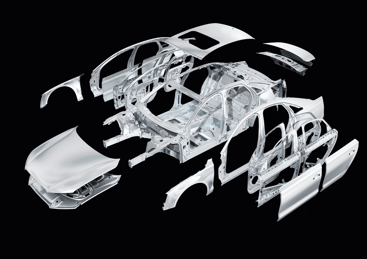
The CAD (Computer Aided Design) model, also referred to as the “math model,” is the engineering and procurement authority for a product’s design definition. RPS alignment emerged from the automotive industry and the complex tasks associated with assembling the many parts making up the “Body-in-White” (BIW). The array of individual panels, primarily sheet metal stampings, must be designed, referenced, and measured throughout the product manufacturing cycle using a clearly defined process. The need was to ensure the components fit together as each part is added to the assembly, and that form, function, and gap-and-flush elements are as perfect as possible to achieve a high quality finished product. By establishing a production philosophy and a fully controlled process with the Reference Point System and its dependent RPS Alignment technique, OEMs are confident they will have a synergy throughout design, manufacturing, sub-contracts, and quality assurance, to maintain accuracy, consistency, and reliability.
Automobile body panels are complex shapes, and further complicating the task of fitting them together is the fact that they are not fully rigid and typically are somewhat flexible. They can change shape simply under their own weight, or during tactile probing. The tolerances for the typically stamped sheet metal panels are necessarily more generous than parts machined from billet, for example. This further necessitates the need for something like RPS Alignment.
The need to employ an accurate, reliable reference system for the automobile “Body-in-White” (BIW) creates a need for the RPS (Reference Point System) Alignment to keep it all tied together via a unified and controlled system.
RPS Alignment strategies control the orientation, translation, rotation, and origin for each component of the assembly. These elements often have their own “component reference system,” which is in turn referenced from the global reference system referred to earlier. (Note: In the CAD/CAM/CAI world the component reference system is often referred to as the WCS or Work Coordinate System. It might also be called the part or local reference system.) Especially when parts do not have a general orientation, or mounting features that are parallel to the global reference system’s three primary planes, it becomes necessary to establish a local component reference system, and a RPS Alignment specific to that part. The engineering drawing or CAD [REF] will have a table of reference point values that represent nominal “datums” on the component to be matched with corresponding measured points from the component [DATA]. Points can be in the form of Surface Points, Profile Points (edge or EOP profile, such as profile of a line), or Feature Points (derived or constructed points such as circle or slot centerpoints). Feature planes or axes can also be used for RPS alignment controls.
The Basics of RPS Alignment
Dimensional Management
This description from Porsche Engineering Magazine of Dimensional Management is a good foundation for explaining RPS Alignment:
“Why dimensional management? The ever more demanding requirements on products in terms of design, appearance, and function led to the development of dimensional management, a preventive quality assurance method that ensures the functionality and producibility of designs at an early stage. Dimensional management makes it possible to avoid potential problems before they occur. It enables engineers to fulfill required quality characteristics (joint scheme) and safeguard points of constriction and critical functions.” 1
Reference Point System (RPS)
Recognizing the need for the precision definition and control provided by a Dimensional Management system, the article provides more insightful information by clarifying the measurement structure defined by the “RPS:”
“Reference Point System (RPS) – The comprehensive Reference Point System (RPS) for the individual parts and assemblies up to completion of the product is the foundation for dimensional management. It is the basis for creating tolerance concepts and measurement planning as well as for the assembly concept. The task of RPS is the precise positioning of a component / assembly in free space and the limitation of the six degrees of freedom (three translational and rotary directions of motion each) using the 3-2-1 rule. This applies to all fixed systems. For kinematic systems, the degree of freedom for the component that causes a motion must remain unrestricted. The RPS points should be in stable areas and ideally parallel to the component coordinate system in their alignment. An adroitly positioned RPS can enable tolerance effects in places that are neither of a functional nor customer-specific character.” 1
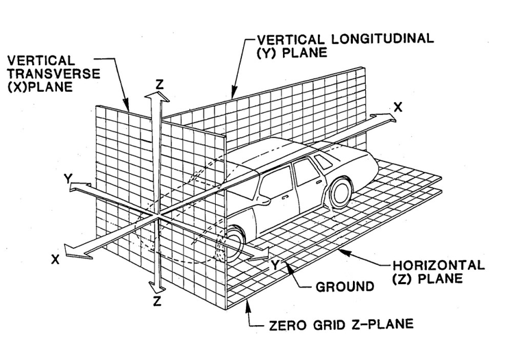
2 RPS (Reference Point System) – example of a typical automotive-type system with origins, axes, and orientations.
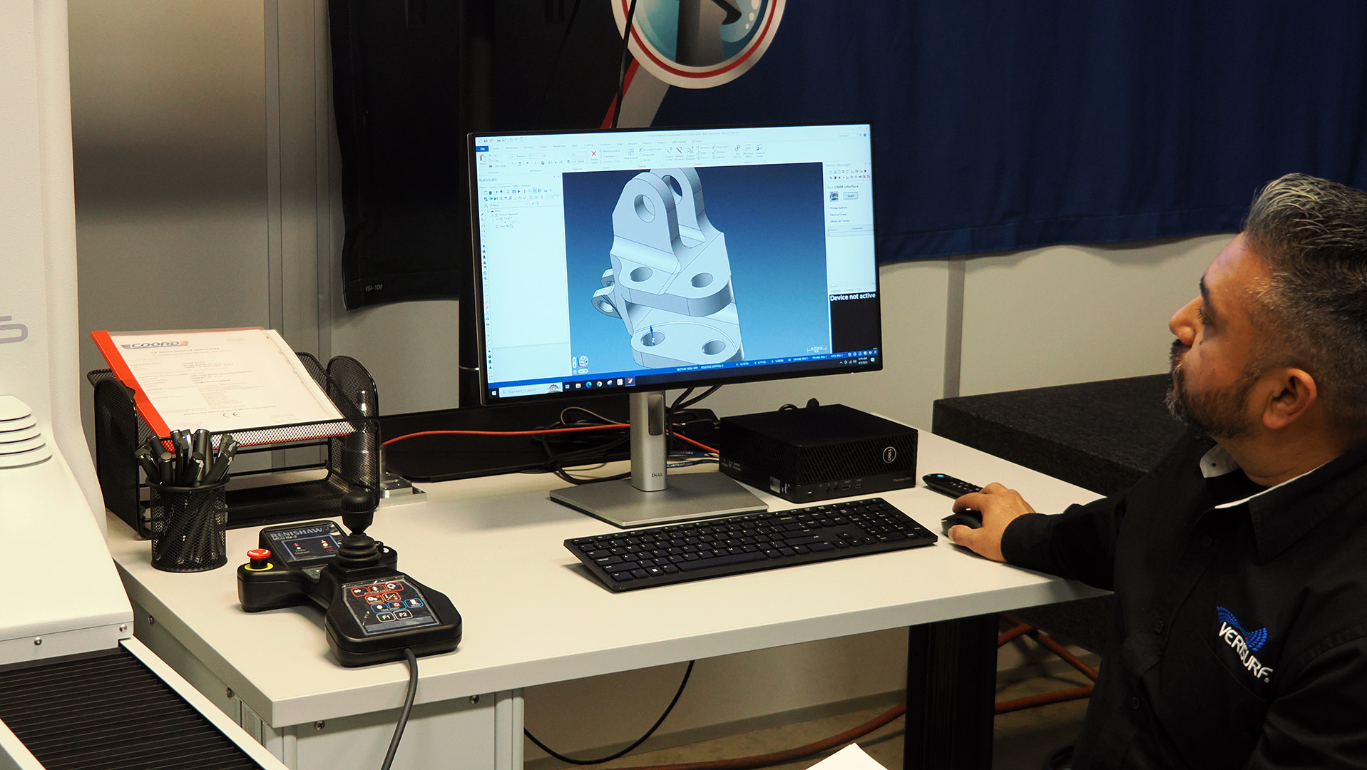
Aligning Workpiece to CAD with RPS Alignment
For CAD-to-part RPS alignment, the metrologist utilizes the metrology software’s RPS Alignment feature to enter point values and/or select datum features per the engineering drawing or model. Verisurf software has options to copy/paste or file/import to bring in the RPS alignment target values, and also has easy selection of features from CAD for the alignment datums as required.
The metrologist must follow the guidelines of the engineering provided to set values or select features from CAD, then set controls for orientation and locks to comply with the 6 degrees of freedom designated by the engineering.
What’s significant about RPS alignment is the engineering-designated points or features to be used as alignment datums, specifying how a part is to be aligned to its component reference system (or WCS), which is ultimately tied to the vehicle (or other assembly) global reference system.
RPS Alignment for Scanning Inspection
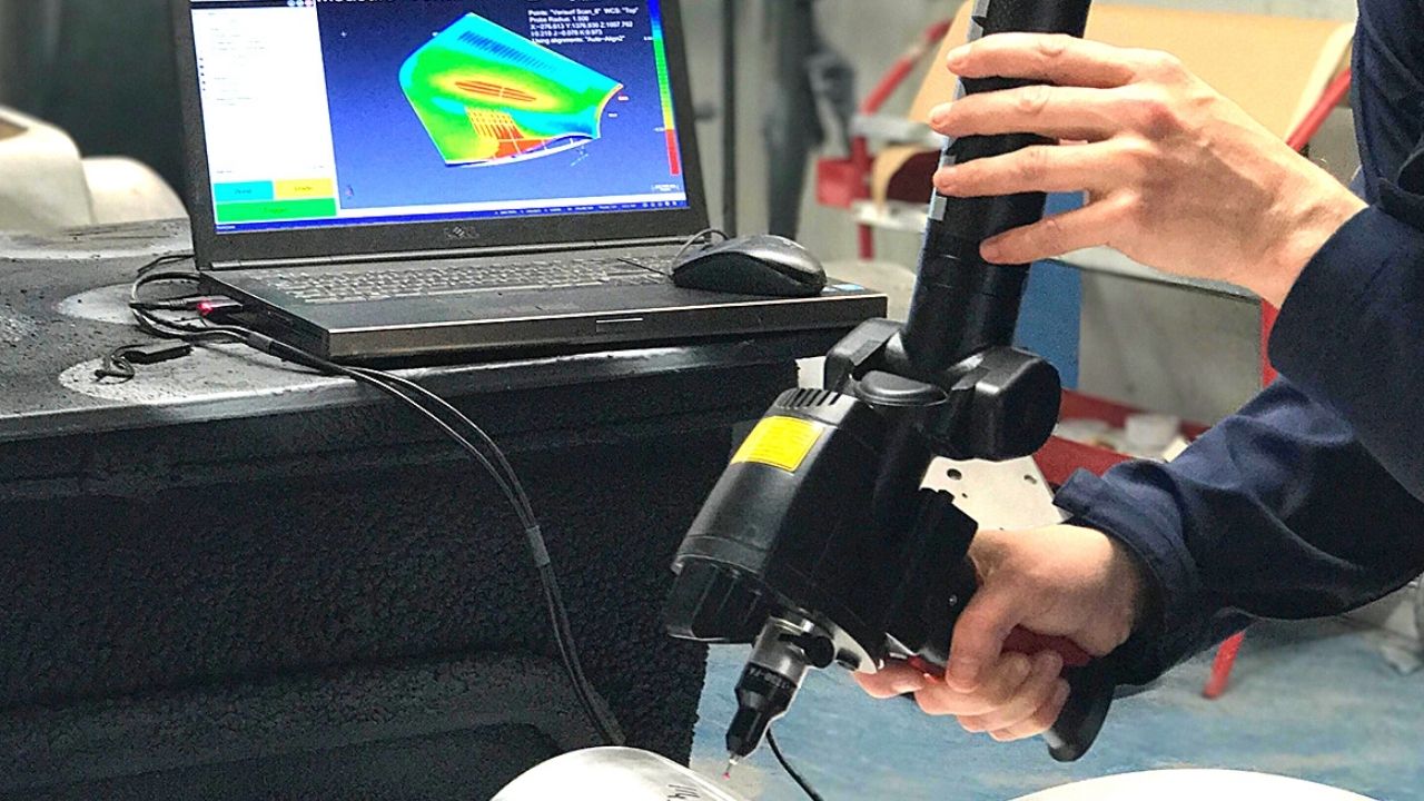
Following is an example of a typical RPS Alignment for a basic scanned part workflow in Verisurf software:
Scan the part or import a scanned dataset and import the CAD model.
For scanning systems such as CMM arms that have a hard probe, or automated CMMs with a touch probe, it is good practice to perform a datum alignment before scanning. In such cases, the best-fit step described below is unnecessary.
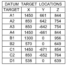
Create a Verisurf AUTOMATE Plan and pick the datum features from the model. If no model exists, create features using the Features toolbar. Use Construct Features as required. If entering the RPS Alignment reference point values manually (like from the sample chart below), use the Details Pane to type in the values. (If selecting from CAD, the software gets the nominal values from CAD.)
Verisurf Productivity Tip: If the model contains MBD (Model-Based Definition) for the datums, you can right-click the datums in the MBD Manager, and select “Plan-Create Plan” from the MBD (Create Plan from MBD video). The RPS Alignment datum features will be automatically added to a Plan.
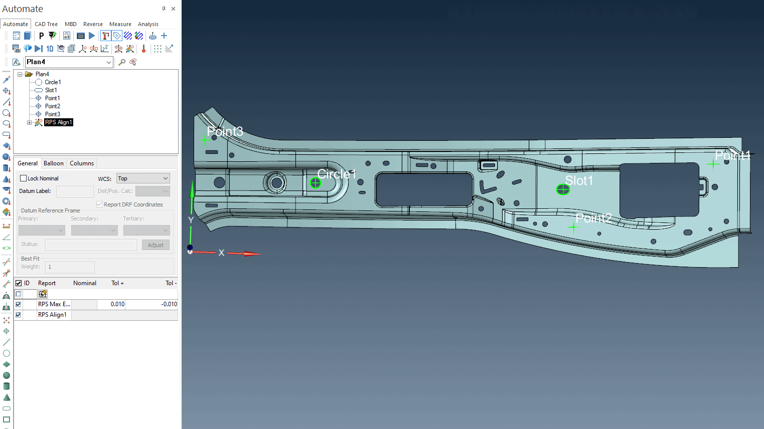
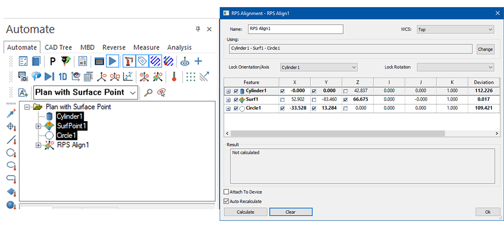
Select the features for the alignment from the AUTOMATE Manager tree, and click RPS Alignment from the AUTOMATE toolbar. Set feature locks in the RPS Alignment dialog. Also select features for each from the Lock Orientation/Axis dropdown or the Lock Rotation dropdown as required.
Create the measured features from the scan required for the RPS Alignment.
From the MEASURE tab select the cloud, then from the speed menu use Edit Cloud to extract the measured features and points.
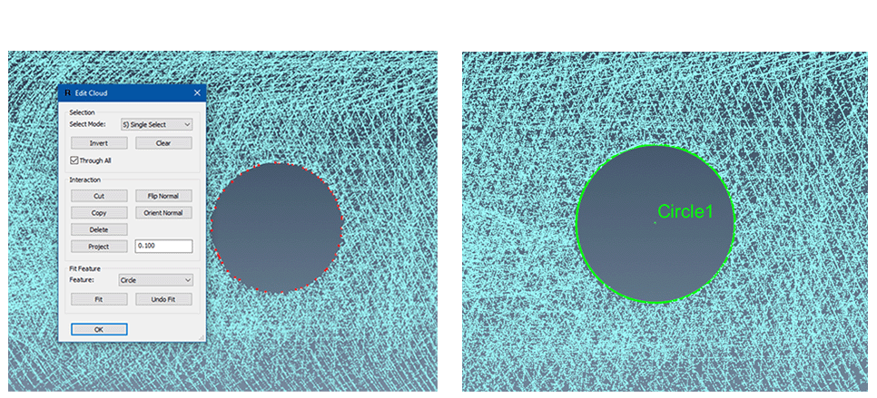
An alternative to creating nominal features in AUTOMATE, is to first create the measured features from the scan, then use them to “Create Plan” from the MEASURE speed menu. Use the same names for the measured features and the nominal features so that they pair as required in the alignment.
Best-fit scan data to the workpiece. The metrology software will do a mathematical least squares fit of the scan dataset to the workpiece and display the results.
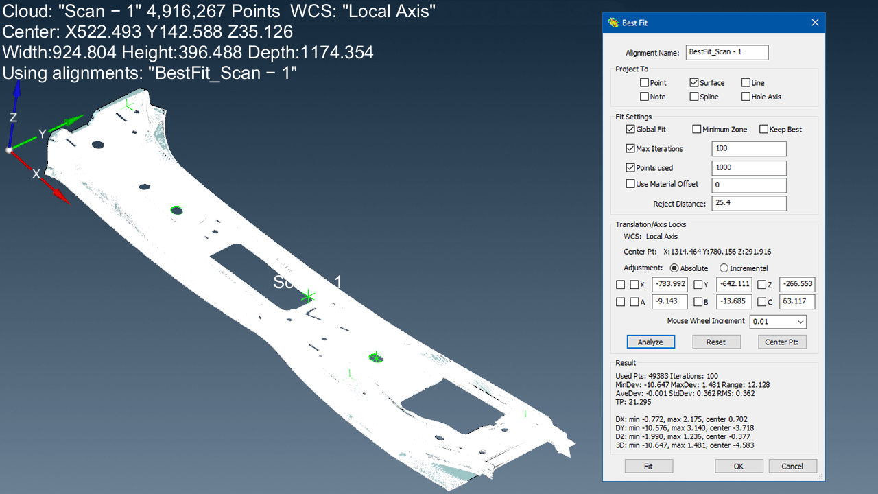
Many part geometries are straightforward for best-fitting, but some parts lack features necessary to adequately constrain all six degrees of freedom for a good fit. The software will have additional tools for a preliminary fit of the scan to the model, including manual drag-and-drop, Global Register, N-Point Alignment, and other techniques.
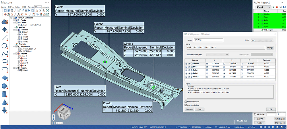
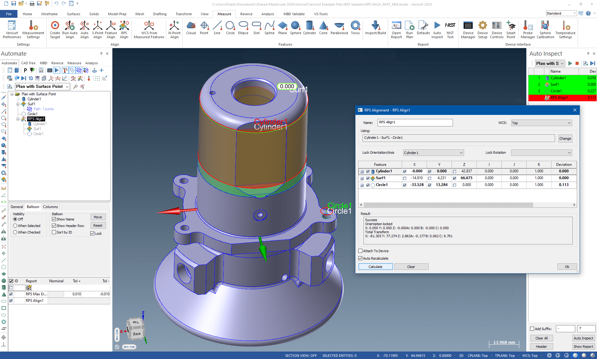
Run the RPS Alignment. Features and points can be automatically or manually extracted from scan and aligned to CAD features or points (datums) in an automated Verisurf Software Plan.
The metrologist must follow the guidelines of the engineering provided to set values or select features from CAD, then set controls for orientation and locks to comply with the 6 degrees of freedom designated by the engineering.
RPS Alignment in CMM Programming and Inspection
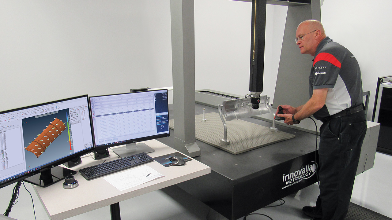
An automated CMM with touch probing and discrete point measuring involves a markedly different process versus scanning, but the RPS Alignment principles and outcome of measured results should be very similar.
Import CAD [REF] model.
Create a Plan (CMM path) in Verisurf AUTOMATE. From the features programmed, select the features for RPS Alignment designated by the engineering, then “RPS Alignment” from the Verisurf AUTOMATE Manager.
Set the axis locks in the RPS Alignment dialog and select features for the Lock Orientation/Axis dropdown or the Lock Rotation dropdown as required, and save as part of the CMM program.
Run the RPS Alignment Plan on the CMM. Automated CMM program executes alignment of measured features and points [DATA] and aligns to CAD [REF] engineering-designated features or points (datums) anywhere in the program, allowing for probe changes, regardless of the program sequence.
The metrologist must follow the guidelines of the engineering provided to set values or select features from CAD, then set controls for orientation and locks to comply with the 6 degrees of freedom designated by the engineering.
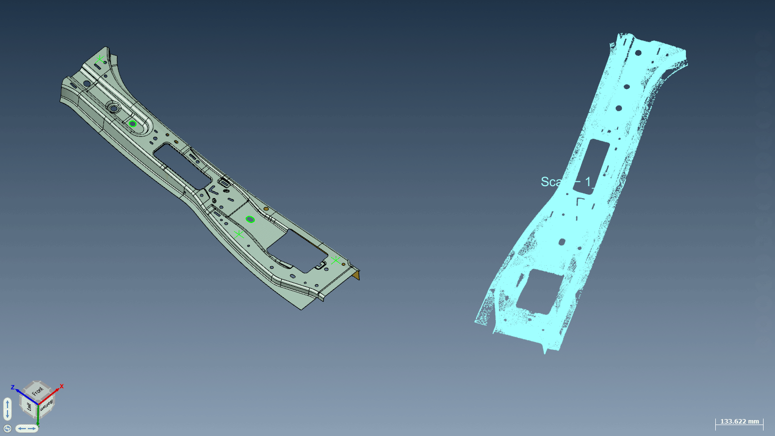
More RPS Alignment Images
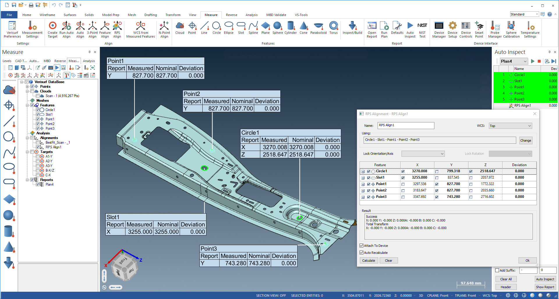
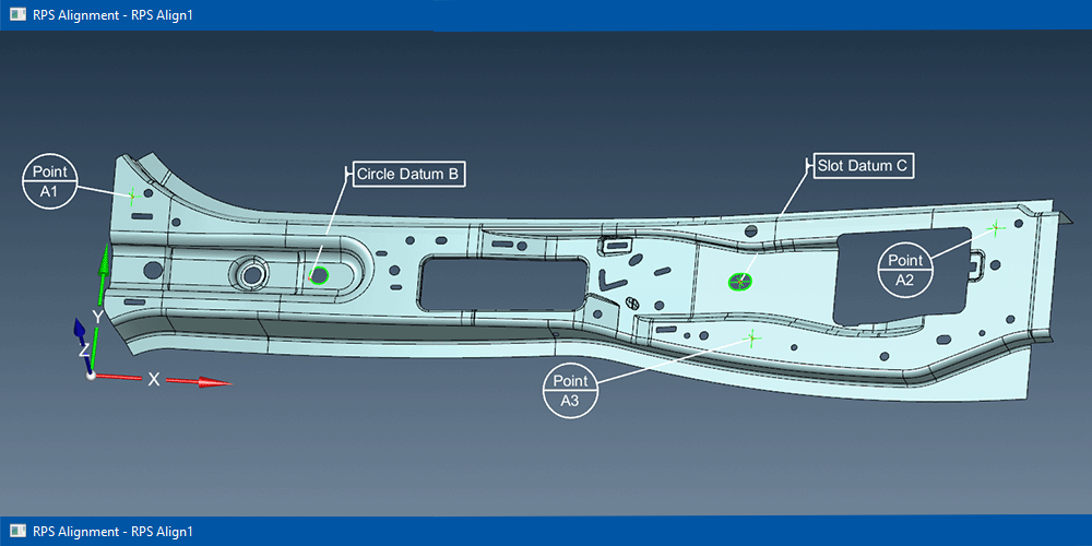
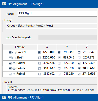
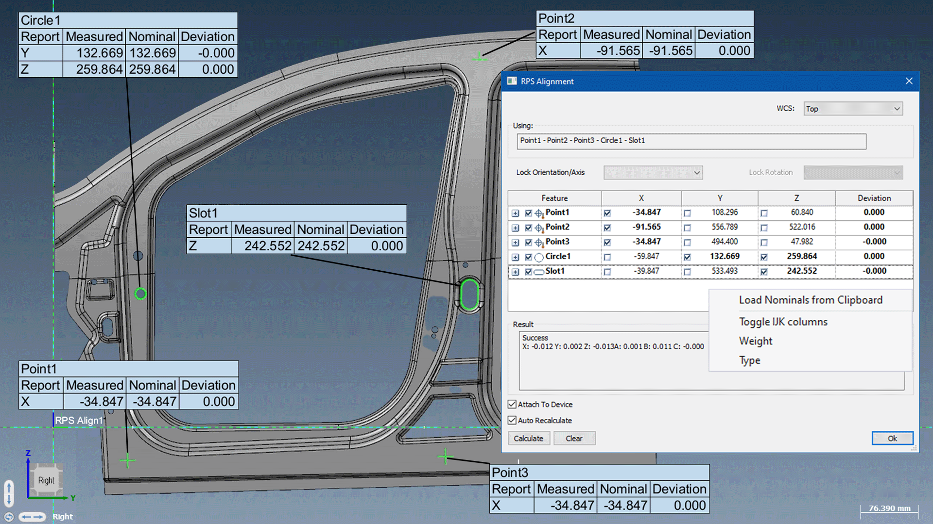
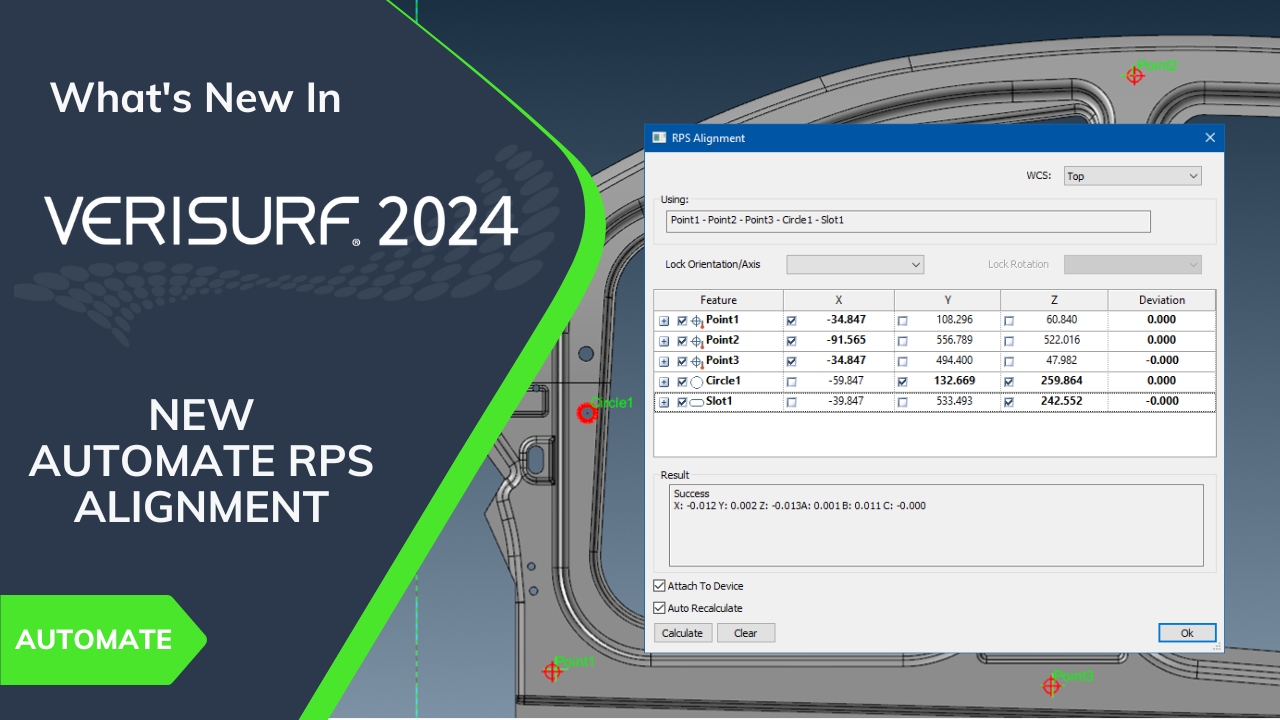
Verisurf RPS (Reference Point System) Alignment performed on an automotive B Pillar, seamlessly connecting the measurements to defined reference points with precise control.
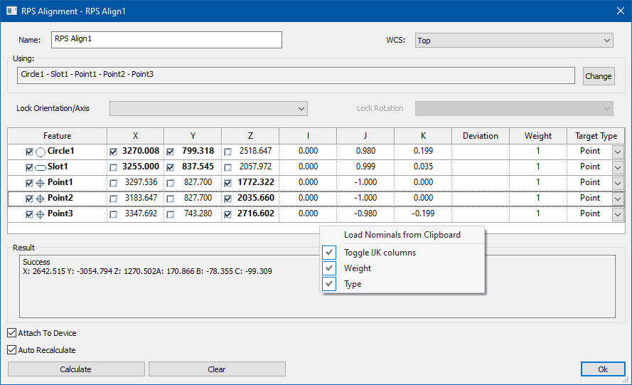
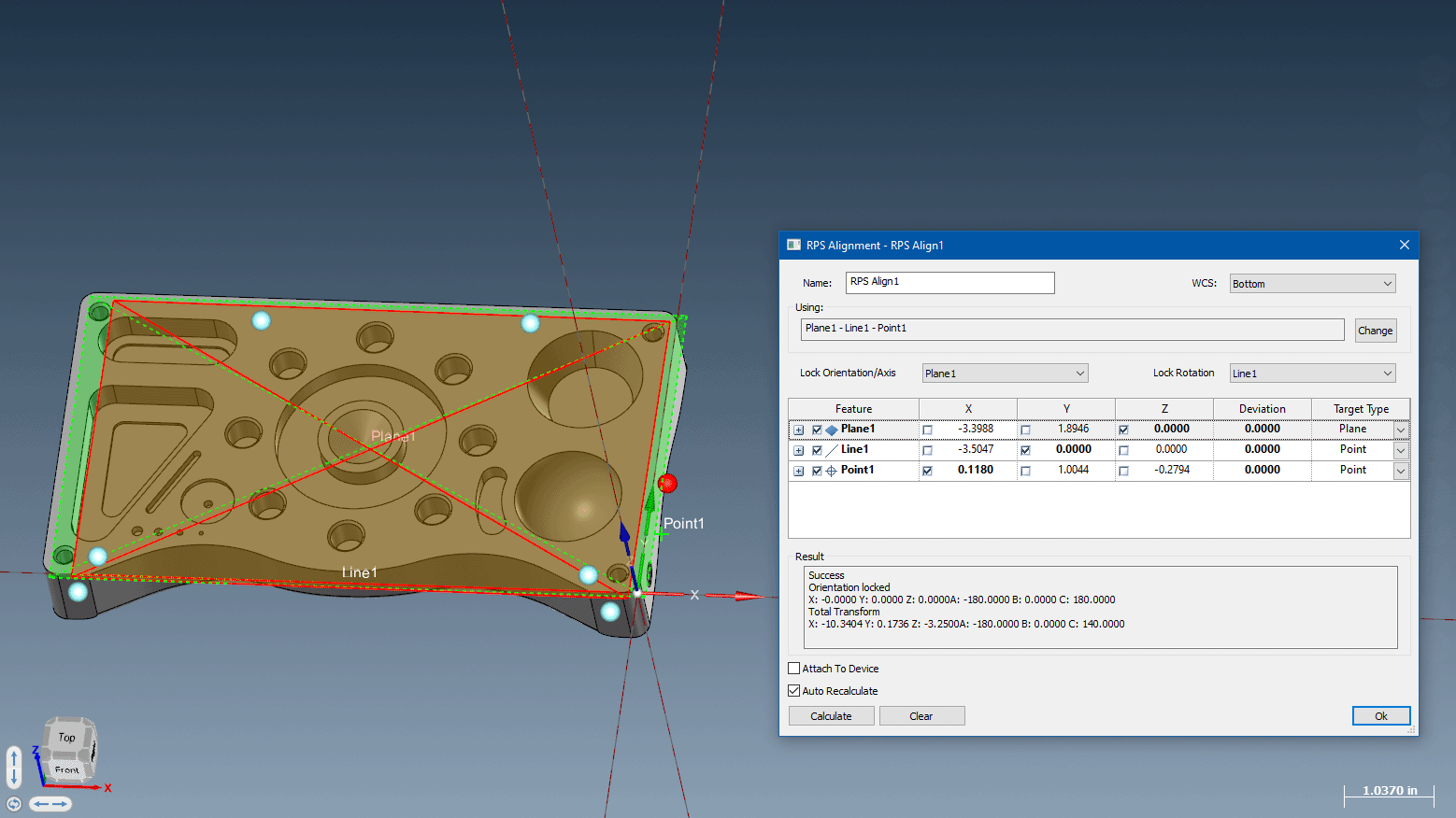
In Verisurf’s RPS Alignment, reference values from engineering drawings or CAD can be copied from clipboard or selected from CAD. Component locks and weights can be easily set from the dialog.
The task of RPS is the precise positioning of a component / assembly in free space and the limitation of the six degrees of freedom (three translational and rotary directions of motion each) using the 3-2-1 rule.1
Examples of Various RPS Alignment Types
Click to enlarge images below, then X to close.
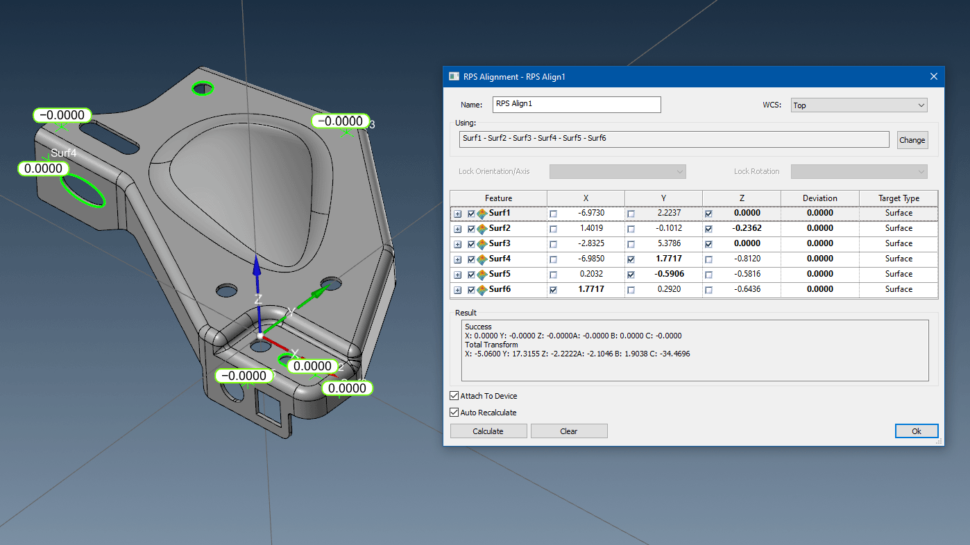
Six Points
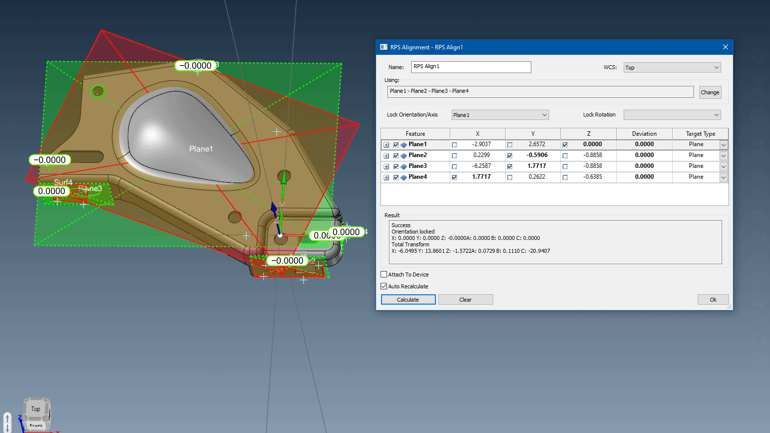
Four Planes
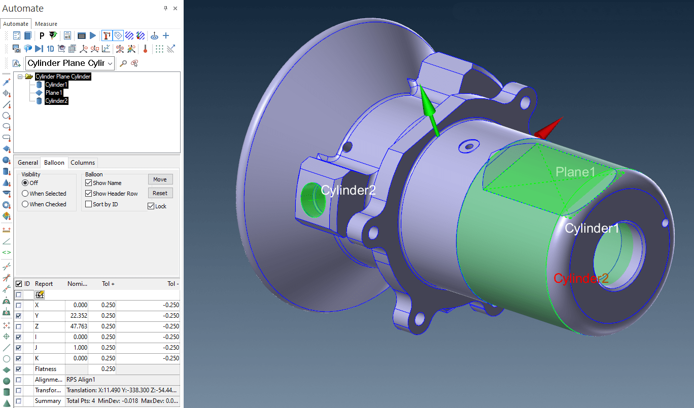
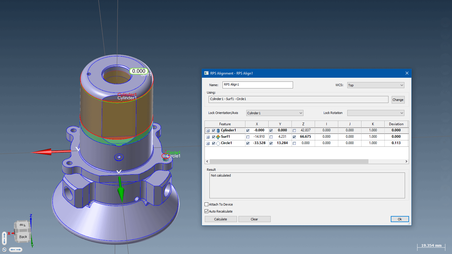
Cylinder Plane Circle
Plane Line Point
References:
1 Porsche Engineering Magazine, “Dimensional Management in Vehicle Development,” By Bernhard Mölzer, Michael Strobelt, (date unknown).
2 SAE Society of Automotive Engineers, Supporting Doc J1100 REV. FEB 2001, SURFACE VEHICLE RECOMMENDED PRACTICE, Sept 1973 Rev Oct 2002
3 International Journal of Scientific & Engineering Research, Volume 7, Issue 9, September-2016, Pgs 562-570, “RPS Alignment of Automotive Body Parts in Virtual Assembly and Deviation Analyses,” Bibek Rai and Liu Shenglan.
Verisurf RPS Alignment Benefits
Verisurf combines the power of Auto Align and Feature Align into a RPS Alignment for inspection plans. RPS alignment works with points, features, constructions, and surface points, making it easy to align to virtually any datum scheme in a plan. This alignment eliminates the need to create a WCS and it allows a feature’s axis to be locked to its nominal value. Measured points can be aligned to nominal points or to planes and surfaces. The centerpoints of features can be fixed to their nominal locations and the axis of directed features such as planes, lines, and cylinders can be used to establish orientation or to lock the rotation around another feature’s axis. XYZ component locks and target weighting enable very precise control of the alignment.
RPS Alignment works with previously measured points, features, and surface points, making it easier to add probe changes, go-to points, and device station moves between measured features in a plan. RPS alignment brings about a simplified approach to alignment strategies benefiting various industries such as automotive and others.
In Verisurf, when you select the Features/Points to use for the RPS Alignment, Verisurf automatically recognizes the best axis direction to lock for each Feature. These locks can be edited, and the RPS Alignment recalculated as required.
By adopting RPS alignment, companies can optimize their workflows, reduce complexities, and enhance overall productivity. This advancement is particularly valuable for the automotive industry where precise alignment is crucial for components and systems to function correctly and effectively.