
Tech Tip – Discrete Point Surface Inspections
When inspecting surfaces of a part or a tool it may be necessary to rework a surface to achieve design tolerances. When the rework has been completed a new inspection must be performed to ensure the entire surface meets profile tolerances. For many years this process was extremely challenging as the measurements taken after the rework process may not always be recorded in the same locations, thus causing additional rework and inspections. To improve the efficiency of these type of measurements Verisurf Software, Inc. has developed multiple methods that allow the operator to use the locations of the initial inspection for all subsequent inspections, this allows the Inspector to measure the same location on the surface every time regardless of the type of measurement equipment being used.
This measurement process is known as; measuring discrete points or ‘search and destroy’ is particularly useful when using a Laser Scanner as the operator must only pass the scanner over the points for Verisurf to record the point data. Using a manual probing device can require patience depending on the number of points and the size of the part being measured.
Define the Nominal Surface Points
In order to perform this measurement task, the operator must define where the points will be measured; points can be defined through Measurement or by using any one of the Verisurf Surface Point Tools that are found on the Analysis Ribbon Bar.
Create Surface Points
Using the Verisurf Surface Point tools found on the Analysis Ribbon Bar the operator can pre-define locations on a Surface and select to save the result as an Analysis or directly to a Plan. Saving directly to a Plan allows the operator to skip the step “Create and Inspection Plan” and immediately run the Auto Inspection to improve the efficiency of the inspection process.
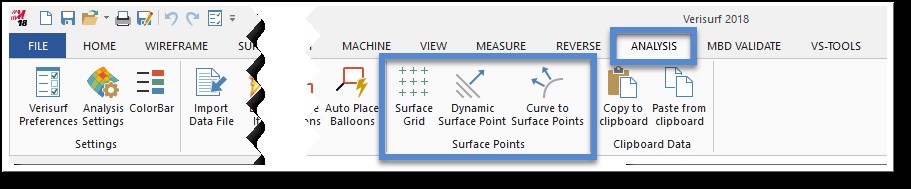
- Access the Analysis Ribbon Bar and select one of the Verisurf Surface Point Tools. See the Analysis Reference Guide for details on using the Surface Point Tools.
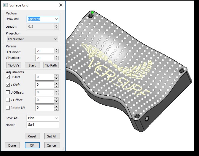
- In the Surface Point dialog (Surface Grid shown on right) select to Save As; Analysis or Plan.
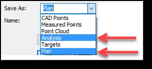
- Save As: Analysis – requires creating Plan prior to measurement, but allows you to customize the Analysis Settings prior to creating the Plan.
- Save As: Plan – creates a Plan in the Data Tree that contains an Analysis object with the defined Surface Points.
Measure the Surface
After aligning to the Tool or Part using the designed Datum Reference Frame (DRF), measure the surface being inspected using the Inspect/Build Mode. Note: Projection Settings must be correct and using the Filter Settings (Containment Boundary, Minimum Distance, Grid Slice or Polar Grid Slice) if desired controls the location and number of points collected for the Surface Inspection. Using Interpolate and Post Filters in conjunction with the other Filters allows you to collect a cleaner more organized Analysis Group.
In the example below; the Verisurf Demo Part is measured using a Grid Slice set at 0.400 in X and 0.400 in Y and a Post Filter Minimum Distance Setting of 0.100” this provided an organized pointcloud ideal for repetitive inspection processes:
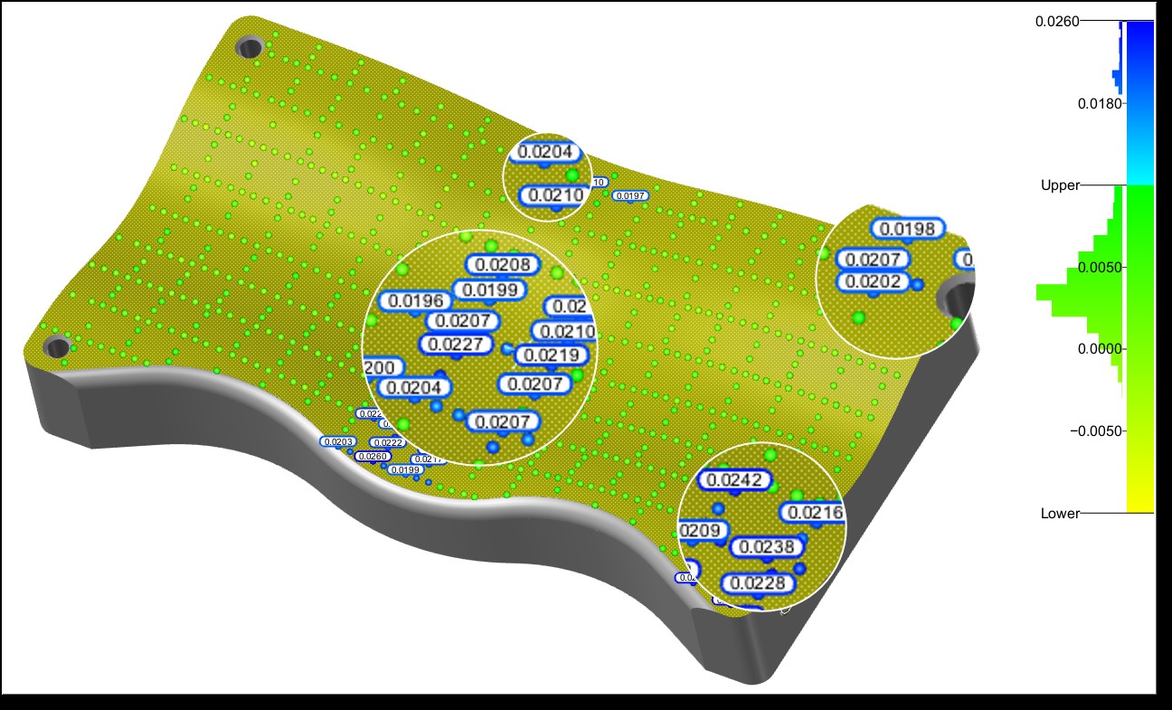
Above – Analysis collected using Inspect/Build X, Y Grid Slice
Create an Inspection Plan
In order to measure the same point locations in consecutive Inspections we can utilize an Inspection Plan, this allows us to measure only the points that are defined on the Surface. By placing the Analysis object in an Inspection Plan, and adjusting its Measure Settings the operator may execute the Inspect Plan and record only the points in the Analysis object in their nominal location; the location of the initial measurement. Use the following process to create the Inspection Plan:
- Select the Analysis object in the Data Tree and access the speed menu with a right mouse click and select Plan – Create Plan.
- In the Measure Manager Data Tree, double left mouse click (DLMC) on the Plan that is now stored in the Reports node.
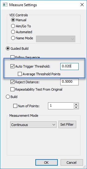
- When the Report Manager opens, DLMC on the Analysis object to open the Measure Settings dialog and adjust the Guided Build Settings for Auto Trigger Threshold to 0.020” when using a Laser Scanner and 0.050” when using a handheld probe. This value controls how close to the point the Scanner Line or Probe must be to the target to execute the
measurement. When using a handheld probing device, a tight tolerance (low number) will result in a labor-intensive measurement process as you attempt to hit the “target”. - Select OK to store the settings.
- Select OK in the Plan to close the Plan.
Run the Inspection Plan to Measure the Surface
The Inspection Plan will now be run from the Auto Inspect Manager found on the Measure Ribbon Bar or the Measure Manager Toolbar.
- In the Auto Inspect Manager select to Clear All and then choose Auto Inspect, all the Surface Points previously measured are now displayed as “targets” as shown below.
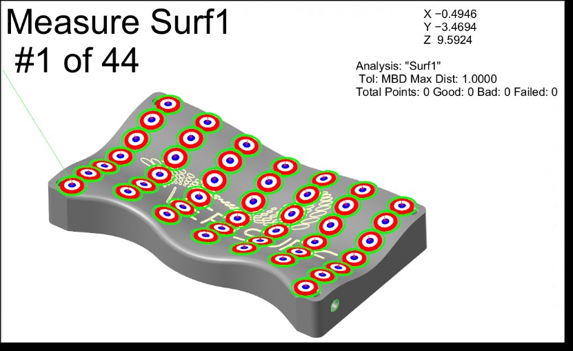
Above – Points displayed as Targets when Inspection Plan is executed.
- Using a Scanner or Probe begin measuring. There is no need to push any device buttons Verisurf automatically recognizes and records the coordinate data as the device moves within the Threshold Tolerance of the target.
- When complete the Auto Inspect Plan will automatically terminate and display the results using the current Analysis Settings display parameters.
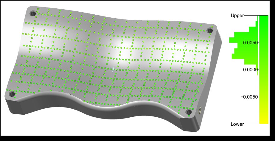
Above – Completed Inspection Plan, all points in tolerance.
Complete the Surface Inspection
Once the surface has been reworked and the inspection process completed successfully, the operator can create an Inspection Report using only the Analysis object from the final surface inspection. The Analysis object’s appearance may be customized to include Lines, Arrows, Cones, Point Probes, Deviations or Color Mapping as required with a screenshot of the Analysis object also added to the Report.
Once the report is formatted to meet inspection requirements a paper report may be printed or results can be saved to a Database if required.
Verisurf Software, Inc.
Verisurf Software, Inc. is an advanced three-dimensional measurement solutions company committed to delivering advanced computer-aided inspection and reverse engineering solutions. Verisurf software helps manufacturers of all sizes and industries produce higher quality products in less time and at a lower cost with automated, Model-Based Inspection processes. For more information, visit the Verisurf website at https://verisurf.com.