
Tech Tip – Compensating for Thermal Expansion
Working in environments that are not temperature controlled can produce measurement errors due to the temperature of the object being measured. When the object temperature varies from the standard 20˚C or 68˚F the dimensions of any part will change based on the physical properties of the material. This variable is calculated by the Coefficient of Thermal Expansion (CTE). Formula: Material coefficient x Temperature deviation from 68°F x Length in inches.
Example: 240 inch piece of Aluminum @ 80° 0.0000130 X 12 X 240 inches = 0.03744 = 240.03744
Note – In Verisurf it is possible to Scale Points, Pointclouds, and Features during the measurement process using Temperature Settings in the Device Manager. It is also possible to Scale after the measurement process has been completed.

It is easy to see that a small temperature change in material can equate to large distance errors between points. In the case of measurement tasks that involve the measurement of points and comparing to nominal values, compensating for part temperature is critical.
CTE during Measurement in Verisurf
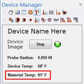
In Verisurf, the compensation for material temperature (Scale) can be done during the measurement process; the active material temperature can be easily viewed in the Device Manager window (shown on right):
Note about Laser Trackers
When using a Laser Tracker, the temperature and air pressure that is entered for the initialization process of the Device is only used to correct the laser’s interferometer measurements back to the standard 68° F or 20° C. This is particularly important to note when distances will be measured between points on an object that is not 68° F or 20° C.
It is a typical misconception that this entering of Temperature accounts for Part Temperature as well, when in fact; it is only used to ensure the Laser Tracker measurements are accurate.
Temperature Settings in Verisurf
Using Temperature Settings applies a Correction Scale Factor to the measurement device, all measurements taken after applying a Correction Scale Factor are therefore compensated for the currently entered material temperature.
The type measurement task determines whether the part temperature must be considered. If the task requires you to verify
distances or dimensions on a part that is NOT 68° F or 20° C you must “Enable Material Compensation” in the Temperature
Settings dialog to achieve accurate measurements.
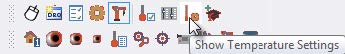
The Temperature Settings dialog controls how Verisurf compensates for the temperature of the object during the measurement process. Temperature Settings is accessed through the Verisurf Device Manager Toolbar only when a Device is active:
NOTE – Changes in the Temperature Settings dialog affect ONLY new measurements, all previous measurements remain unchanged. It is recommended that if Material Temperature must be compensated for the material compensation should be completed at the beginning of the measurement task (before measurements).
Using Material Compensation
In order to use Material compensation for thermal scaling, it is necessary to have one or more temperature probe(s) and an accurate material thermometer.
- In the Device Manager dialog, choose the Temperature Settings button for the active device. Verisurf displays the Temperature Settings dialog (shown below), if a Temperature Device is not detected it will be noted in the dialog.
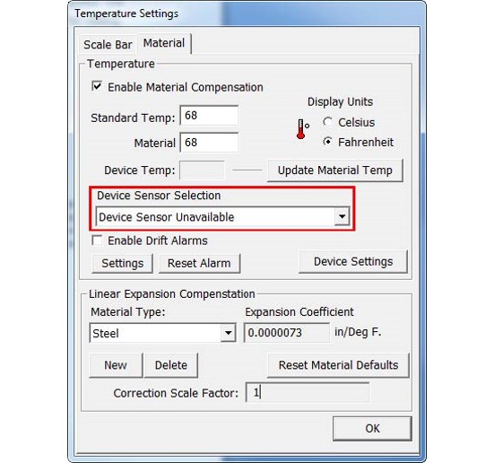
The Temperature Settings Dialog – Material Compensation
- Select the Material tab, and choose Enable Material Compensation.
- Enter the reference temperature in the Standard Temp input. This is typically 20°C or 68°F.
– You can toggle the display units using the radio control marked Celsius/Fahrenheit. - If you know the Material Temperature, enter it; otherwise, your system can be configured to read it electronically.
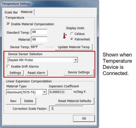
Temperature Sensor Connected
The following options are available if you have a temperature sensor connected to the system:
- Use the drop-down list labeled Device to choose the temperature sensor. The list displays all part temperature sensors installed on the system.
- Select Enable Device Temperature for Material to poll the device for part temperature. When you select this option, Verisurf displays the appropriate settings dialog for the selected device.
- If Enable Device Temperature for Material is checked, you can also choose Auto Update Device Temperature to Material. With this option set, Verisurf will automatically update the material temperature to the temperature of the device.
- Choose Enable Drift Alarms if you have selected both of the previous options and you want Verisurf to warn you if the part temperature drifts outside a preset limit.
Adding a Material Type
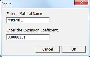
If you want to add a new material-type (and CTE), choose the New button. Verisurf opens the Input dialog:
- Use the Enter a Material Name field to enter a material name, and then enter the Expansion Coefficient in the designated input field
- Choose OK to close the Input dialog.
- Verisurf adds the material to the list.
- You can use the Delete button to remove the current material from the list.
– The Correction Scale Factor in the Temperature Settings dialog are the values entered in the Input dialog. - Choose the OK button to close the Temperature Settings dialog.
Verifying Scale of a Device
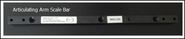
Determining whether a Device is measuring distance (scale) accurately can be accomplished using a Certified Scale Bar, these Scale Bars come in a wide variety of Material types. To perform this check the Scale Bar must be of the same material as the object, and be acclimated to the same temperature as the object being measured.
After applying the Material Compensation (see next section) the Scale Bar may be measured and the distance between the points compared to the calibrated distance of the Certified Scale Bar.
Note – it is common practice when using a Laser Tracker to verify Scale Bar distances after the Alignment has been calculated, due to the ability to “Scale” Auto Alignments and 3- Point Alignments.
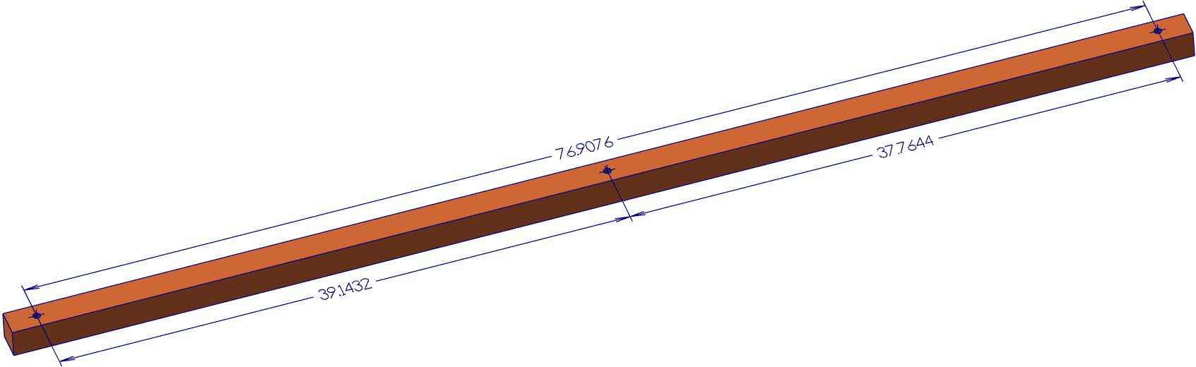
Above: Laser Tracker Scale Bar with Three Certified Distances.
CTE after Measurements
When Points and Features have been measured using the Standard 68˚F or 20˚C Material Temperature but the object temperature varies it is possible to correct the measured Points and Features for temperature after the measurement process has been completed.
This process utilizes the Temperature Settings dialog box to perform the Scale Factor calculation that will be entered into the XForm dialog.
Calculate the Scale Factor
Prior to beginning the scaling procedure measure the object Temperature with an accurate (certified) thermometer.
- Open the Temperature Settings dialog from the Device Manager (device must be active):
- In the Temperature Settings dialog
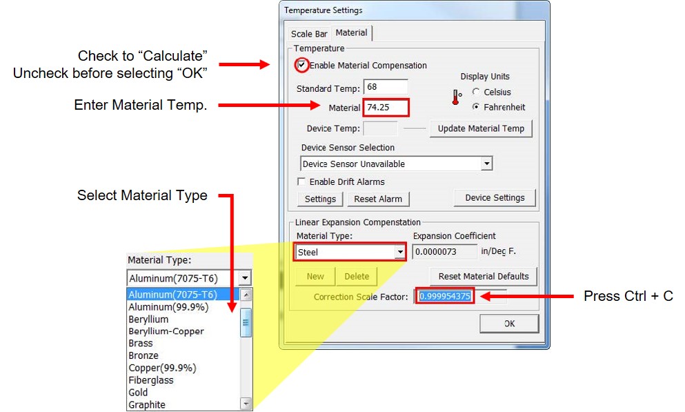
– Enable Material Compensation to activate the Linear Expansion Compensation field at the bottom of the Temperature Settings dialog.
– Enter the Material temperature,
– Select Material type
– View the new Correction Scale Factor
– Copy the Correction Scale Factor value using Ctrl – C from the keyboard. - After copying the Correction Scale Factor, disable the Material Compensation check box.
- Select OK to exit the Temperature Settings dialog, continue to the next section.
Use the Correction Scale Factor
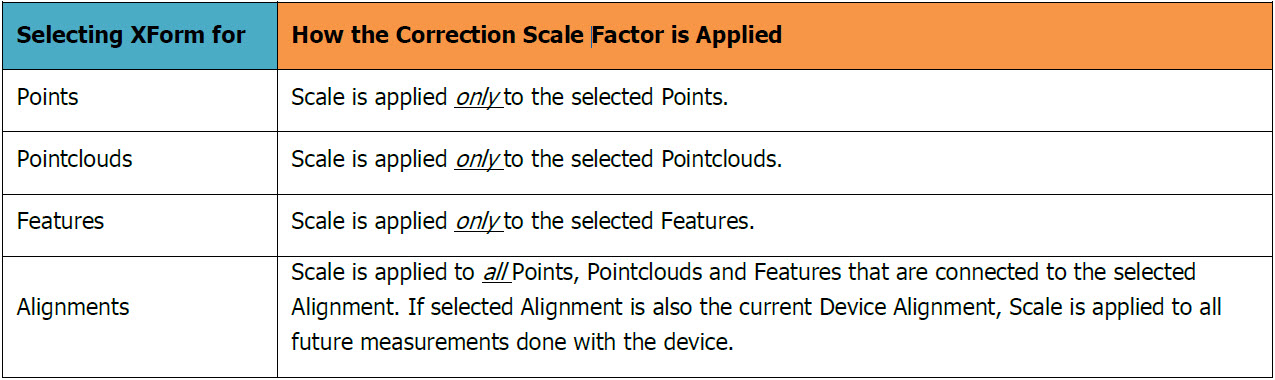
The Correction Scale Factor can be applied using the XForm dialog box found in the speed menu of Points, Pointclouds, Features, and Alignments in the Measure, Analysis, and Reverse Managers.
Depending on the application the Correction Scale Factor (Scale) can be applied as follows:
Applying Scale to Points, Pointclouds and Features
In the Measure/Analysis/Reverse Manager it is possible to apply a Scale Factor to single or multiple Points, Pointclouds or Features using this process:
- In the Data Tree select the Point(s), Pointcloud(s) or Feature(s) to apply Scale Factor.
- Using a Right mouse click accesses the speed menu, select Tools – XForm to open the XForm dialog.
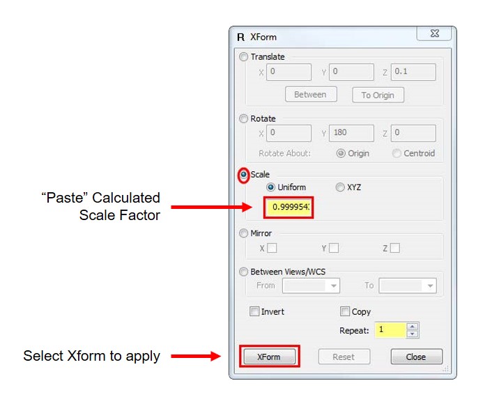
- Using the Correction Scale Factor that was “copied” in the previous section (Calculate the Scale Factor) paste the value into the Scale field as shown, then select the XForm button, close the dialog all selected points, pointclouds and features are scaled:
Applying Scale to an Alignment
Using XForm to Scale an Alignment offers the benefit of quickly scaling all Points, Pointclouds, and Features that are currently connected to the Alignment. If the selected Alignment is the active Device Alignment all future measurements will be correctly scaled during the measurement process.
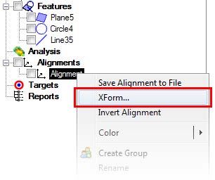
- In the Measure, Analysis or Reverse Manager select the Alignment to apply a Scale Factor.
- Using a right mouse click select XForm
- In the XForm dialog, “paste” the Correction Scale Factor that was calculated in the previous section (Calculate Scale Factor) into the Scale field, select the XForm button then Close the dialog:
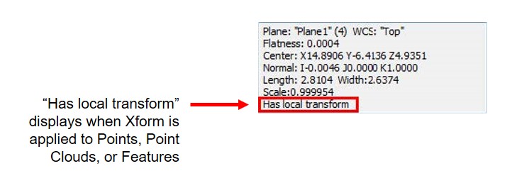
- After the Scale has been applied in the XForm dialog the Alignment in the Data Tree is shown with the applied Scale Factor when viewed in the Statistics box (shown below).
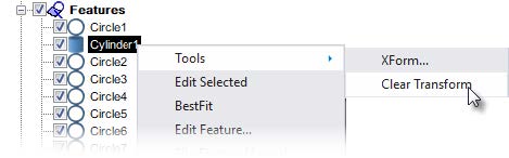
NOTE: At any time you can “Clear Transform” using “Tools” in the speed menu.
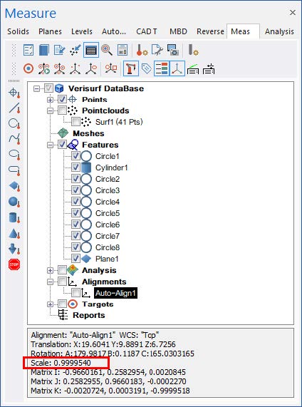
Note – All Points, Pointclouds, and Features connected to the selected alignment are scaled. If the active device is
connected to the Alignment all future measurements will be scaled.
Verisurf Software, Inc.
Verisurf Software, Inc. is an advanced three-dimensional measurement solutions company committed to delivering advanced computer-aided inspection and reverse engineering solutions. Verisurf software helps manufacturers of all sizes and industries produce higher quality products in less time and at a lower cost with automated, Model-Based Inspection processes. For more information, visit the Verisurf website at https://verisurf.com.