Tech Tip – Best Fit a Hole Pattern
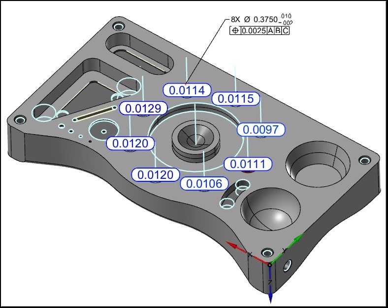
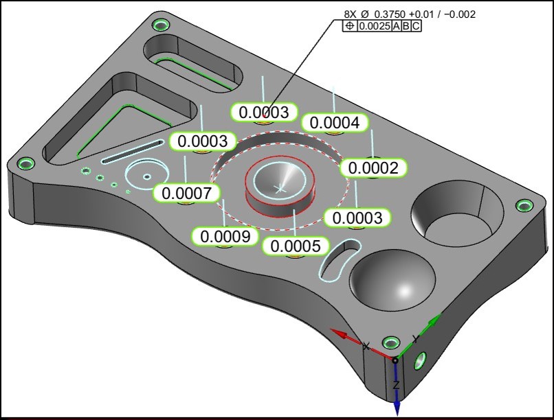
When verifying a Hole Pattern to a Positional GD&T Tolerance it can be very useful to utilize Best Fit to achieve the best possible Positional result when a CAD Model is being used as the Inspection media.
The use of Best Fit is only possible when CAD Nominal information exists, as the Best Fit process requires the use of nominal CAD data for the nominal Hole locations.
Before the Best Fit
Best Fit the Holes
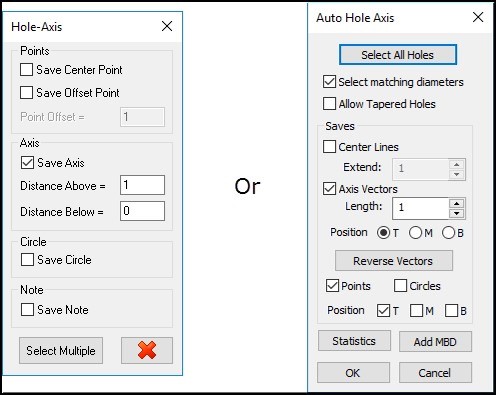
When Best Fitting holes the use of Hole Axis for projecting will yield the best Positional results, if the Hole pattern does not have Hole Axis use the Verisurf Hole Axis or Auto Hole Axis tool (shown right) found on the Verisurf Tools Ribbon Bar menu prior to beginning the Best Fit process. In the Verisurf Hole Axis or Auto Hole Axis tool be sure to select to Save Axis or Axis Vector.
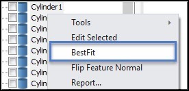
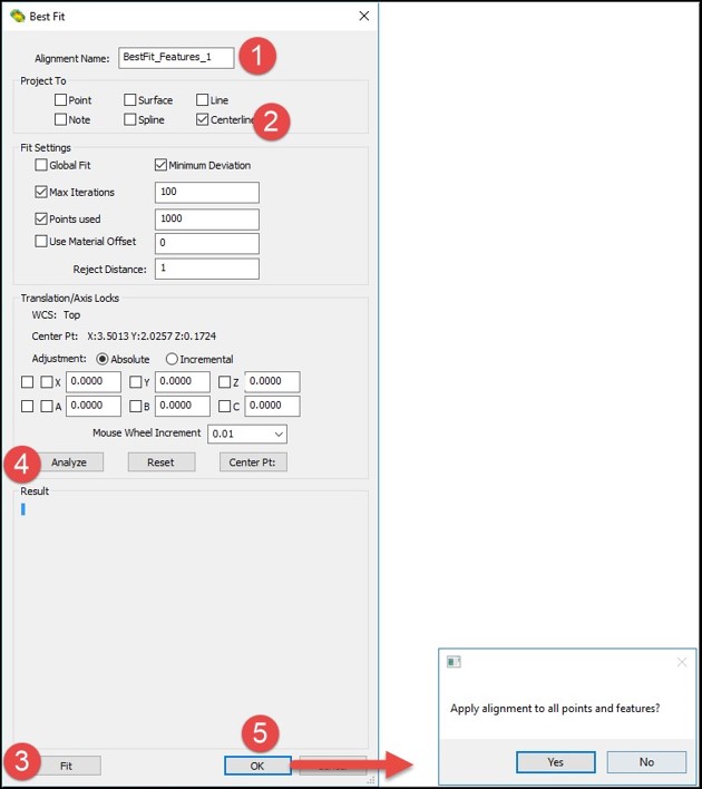
After correctly setting the Project To settings, select the measured Holes in the Measure Manager Data Tree and using a right mouse click access the speed menu and select Best Fit, the Best Fit dialog will open (for more details on Best Fit see the Verisurf Analysis Reference Guide).
The operator will then be prompted to Apply Alignment to All Points and Features – when Best Fitting for hole patterns, the operator should select NO, and then go to the Data Tree, select the Holes and using the speed menu choose Alignment and Connect the Best Fit to the selected Hole Pattern. In this way, ONLY the holes are connected to the Best Fit Alignment and not all the Points and Features in the Data Tree.
Report the Hole Pattern Position
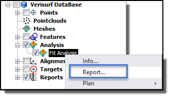
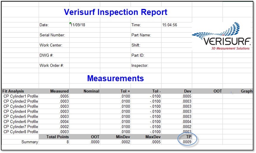
The operator has multiple options for reporting the Position of the Hole Pattern, if ONLY the Positional Error of the eight holes is required the operator may select the Analysis Fit object in the Data Tree and select to Report, this will give the operator one Group in the Report Manager displaying ONLY the Measured Positional Deviations.
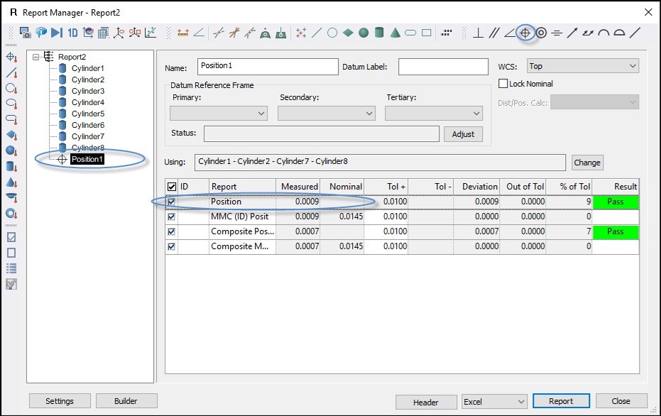
Or if the measurement task requires reporting the information about each individual hole in the Hole Pattern inspection the operator may select all eight Holes in the Data Tree and using a right mouse click select Report.
Once in the Report Manager (below), the operator must select all eight holes and then select to Report Position from the GD&T Toolbar in the Report Manager.
When generating the Report from the Report Manager the operator may control the details of the report for the holes. For more information on how to Report information see the Measure Manager Help file.
Verisurf Software, Inc.
Verisurf Software, Inc. is an advanced three-dimensional measurement solutions company committed to delivering advanced computer-aided inspection and reverse engineering solutions. Verisurf software helps manufacturers of all sizes and industries produce higher quality products in less time and at a lower cost with automated, Model-Based Inspection processes. For more information, visit the Verisurf website at https://verisurf.com.

