
F-35 Lightning II Fighter Canopy
A Fitting Example of Practical Precision Tooling Using Advanced Metrology
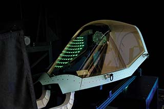
This story is about building and verifying advanced tooling. Form tooling and fixturing as a manufacturing concept has spanned the ages and today remains at the foundation of creating many advanced parts, including the cockpit canopy for the most advanced aviation platform ever created, the F-35 fighter jet.
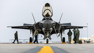
The canopy is built to withstand the impact of a 4-pound bird at 480 knots on the reinforced windscreen and 350 knots on the canopy crown without breaking. Specialty coatings are applied to the finished canopy to maintain low-observable or stealth characteristics. (Image courtesy of the United States Air Force)
The complexity and precision of today’s composite parts rely heavily on the layup tools that make advanced forming possible. The layup tools and those who design, manufacture, and inspect them are the unsung heroes behind the many parts and finished products that rely on high strength, lightweight composites.
As with most manufacturing applications there is constant improvement in materials and processes that make turning out high tech parts faster and cheaper with ever improving quality. Throughout this ongoing evolution one thing seems to remain constant, layup tooling is at the foundation of both functionality and quality. There are many hand-offs in the manufacturing and assembly of composite parts, which often include machining, coatings, finishing, and add-on components. If the layup tooling is not perfect the foundation is flawed.
NÉOS Technologies (formerly Hockley Pattern & Tool), Halesowen, England is an example of a company dedicated to the art and science of making perfect tooling. At the heart of the UK tooling manufacturing industry for over 25 years, NÉOS supplies high quality tools domestically and internationally to a variety of major aerospace and automotive manufacturers and their supply chains.
“When it comes to designing and making tooling it can be both a creative and highly technical process,” said Neil Williams, Director of NÉOS. “Typically, we receive 3D CAD models which we use to design, build, and inspect finished tooling. But we are often asked to create tooling from an artifact, which can be an organic shape or prismatic part for which there are no CAD models or drawings available. Regardless of how a job comes to our shop, every finished tool includes a quality inspection report tied to a 3D CAD model,” added Williams.
NÉOS Technologies (formerly Hockley Pattern & Tool), Halesowen, England is an example of a company dedicated to the art and science of making perfect tooling.
For NÉOS to fulfill their promise of delivering a CAD model-based quality verification report with every finished tool, they rely on Verisurf software and compatible measurement devices. With the operative term being CAD-based, Verisurf was selected on four compelling points:
- Verisurf software is model-based and built on a CAD platform, including 3D modeling.
- The software provides flexible measurement, reverse engineering (including Class A surfacing), inspection, tool building, and assembly guidance.
- Verisurf software imports and exports intelligent CAD files and models seamlessly and can edit existing intelligent GD&T data. Verisurf can also add new GD&T annotations, as necessary.
- Verisurf supports and runs virtually all digital measuring devices from contact probing to non-contact scanning, regardless of age, controller type or proprietary software, including CNC CMMs, arms, trackers, and all types of scanners.
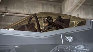
The concept behind the F-35 Lightning II cockpit is to ‘return the pilot to the role of tactician.’ (Image courtesy of the United States Air Force)
The flexible combination of an open software platform and a variety of measurement device options allows NÉOS to develop and/or maintain digital continuity, or digital thread, throughout every job.
“Verisurf software has truly raised our quality control levels with its unique set of application tools that speed up our tooling inspection. We also use Verisurf Reverse, integrated CAD and solid modeller to produce surface models direct from our scanner. The color error mapping and labeling is outstanding and allows us to confirm the accuracy of our work in real time,” said Robin Walton, NÉOS Quality Manager.
F-35 CANOPY—A FITTING EXAMPLE
NÉOS was tasked with building, inspecting, and delivering tooling for components of the canopy of the F-35 Lightning II fighter jet. The job required extremely tight tolerances for the canopy assembly, comprised of frame components and a combined windscreen and canopy transparency. The transparency is produced from a single piece of stretched acrylic, with no steps or gaps in the outside moldline.
The canopy is built to withstand the impact of a 4-pound bird at 480 knots on the reinforced windscreen area and 350 knots on the canopy crown without breaking. Specialty coatings are applied to the finished canopy to maintain low-observable or stealth characteristics.
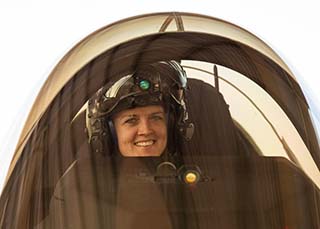
Pilots never see the outside world through the canopy. They see an image of it. (Image courtesy of the United States Air Force)
The F-35 is the world’s second 5th generation tactical fighter designed to satisfy four key objectives: lethality, survivability, supportability, and affordability. The concept behind the F-35 Lightning II cockpit is to ‘return the pilot to the role of tactician.’ This is accomplished by using computers to do what computers do best and allowing pilots to do what pilots do best, with optimum Pilot Vehicle Interface (PVI), manageable single seat workload, and superior situation awareness.
Pilots never see the outside world through the canopy. They see an image of it.
Every manufactured canopy optically distorts the view of the outside world in a unique way. Aerial and ground targets viewed through head-up and helmet-mounted displays can be distorted by imperceptible deviations in canopy thickness, curves, and material. Simply put, the canopy can have a direct effect on weapon accuracy. To mitigate this, every canopy is manufactured and verified to extremely tight tolerances. Each canopy is then optically mapped and matched to a specific aircraft as part of the assembly process with optical deviation data stored in on-board systems to correct the pilots view of the outside world, in real-time.
LIVE BUILD
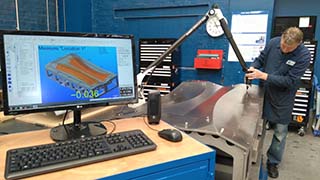
The F-35 canopy layup tool (foreground) is inspected using Verisurf software and a FARO laser tracker.
As part of the tool building process for the F-35 canopy components, NÉOS utilized several key features of the Verisurf software, combined with appropriate measurement hardware devices, to ensure accuracy and quality verification.
Verisurf Build, also known as the Virtual Gage, displays real-time deviation following the movement of a CMM laser tracker or probe, inspecting the part in relation to the nominal CAD model. Following quick alignment to the CAD model, Build’s live, intuitive interface shows part-to-model deviations.
“The software has been a game changer for us by providing not only clear and decisive tooling verification but also live digital tooling setup and positioning for advance tooling applications in our aerospace department,” said Paul Squire, NÉOS Engineering Manager. In addition to dimensional control, NÉOS utilizes the Verisurf Build interface for several additional functions, including:
- Intermediate setup inspection for machining datum establishment to optimize the machining process.
- In process positioning of ancillary components on tooling assemblies with live guided adjustment.
- Tooling point clarification and positional controls.
- Off-site verification and inspection on larger in process tooling build items.
- The ability to live build reverse engineered CAD, especially when carried out off-site, instills customer confidence in raw tooling data prior to final machining.
LOCAL WAVINESS
Every canopy is optically mapped and matched to a specific aircraft. Optical deviation data is stored in on-board systems to correct the pilots view of the outside world, in real-time.
The F-35 canopy is both an aerodynamic component and a lens that transmits and refracts light. Add to this the aircraft’s performance capabilities and piloting objectives and there is little room for error surrounding the entire canopy system. Identifying and minimizing waviness of the canopy tool surface helps to mitigate optical and aerodynamic deviations, maintaining surface performance and lessening the amount of optical correction needed from onboard systems.
A specific feature of Verisurf software is used to determine waviness of the tool surface, both within a local profile and relative to deviations across the entire surface. This provides data to the user to help them correct the tool if necessary.
- Global Deviation Analysis – The first analysis done is the global profile, this gives a deviation map showing the rigid body full point set. This is the standard analysis performed to view the total deviation compared to the nominal CAD model.
- Local Range Analysis– The range is the first Local Profile analysis performed. It determines the total range of the points within the point set analyzed. In the example every point within a user defined radius of 10” is analyzed to get the greatest high/low rage within that local profile.
- Local Deviation Analysis– The deviation of the local profile analysis provides the total deviation from the CAD nominal of the points within the established local profile. This is used to identify and repair high and low spots.
- Local Profile Average Analysis– Averaging the local profile analysis provides an understanding of average deviations inside of the local profile to bench the part for better results.
FINAL INSPECTION AND REPORTING
A SINGLE MODEL-BASED MEASUREMENT PLATFORM
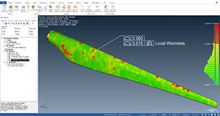
In this example of a 36-foot wind turbine blade, Verisurf is used to identify areas of “local waviness” on the surface profile that need to be corrected. This is done across the entire profile of the part providing both global and localized analysis and reporting.
Verisurf software is an example of integrating modern metrology with traditional manufacturing methods to raise the bar on what is possible. Built on a CAD platform, Verisurf supports natural progression of model-based design, engineering, manufacturing, and quality verification. This maintains digital continuity throughout every he step of the design build process.
“The evolution of tooling in manufacturing has advanced more in the past 20-years than any other period in history,” said Ernie Husted, President and CEO of Verisurf Software. “High tech materials has been a critical contributor, but without the experience of expert toolmakers and the integration of CAD, reverse engineering, and metrology solutions, finished platforms the likes of
the F-35 would not be feasible, today.”
F-35 GENERAL CHARACTERISTICS
Crew: 1
Length: 51.4 ft (15.7 m)
Wingspan: 35 ft (11 m)
Height: 14.4 ft (4.4 m)
Wing area: 460 sq ft (43 m2)
Aspect ratio: 2.66
Empty weight: 29,300 lb (13,290 kg)
Gross weight: 49,540 lb (22,471 kg)
Max takeoff weight: 70,000 lb (31,751 kg)
Fuel capacity: 18,250 lb (8,278 kg) internal
Powerplant: 1 × Pratt & Whitney F135-PW-100 afterburning turbofan, 28,000 lbf (120 kN) thrust dry, 43,000 lbf (190 kN) with afterburner
Maximum speed: Mach 1.6 at altitude, 700 kn (806 mph; 1,296 km/h) at sea level
Range: 1,500 nmi (1,700 mi, 2,800 km)
Combat range: 669 nmi (770 mi, 1,239 km) on internal fuel 760 nmi (870 mi; 1,410 km) interdiction mission on internal fuel air to air configuration
Service ceiling: 50,000 ft (15,000 m)
g limits: +9.0
Wing loading: 107.7 lb/sq ft (526 kg/m2) at gross weight
Thrust/weight: 0.87 at gross weight (1.07 at loaded weight with 50% internal fuel)
For more information about Metrology UK visit https://www.metrologyuk.com/
For more information about NÉOS Technologies visit https://www.neosintl.com/neos-technologies/