
Software Highlights – CMM Programming
Collision Detection and Avoidance
CMM simulation is important for programming, verification, optimization, and preventing damage to capital equipment. Suppose a collision occurs between the probe and the part. The result can be catastrophic for the machine, probe system, and the part being measured.
Collision Detection Controls in Verisurf AUTOMATE
- Toggle Simulate on from the Automate toolbar and choose your device from the drop-down in the Simulate panel.
- Choose your Alignment or simulated WCS alignment from the Alignment drop-down.
- If necessary, adjust placement using XForm then selecting “T” Translate or “R” Rotate the simulated Alignment.
- Select Prepare CD (Collision Detection).
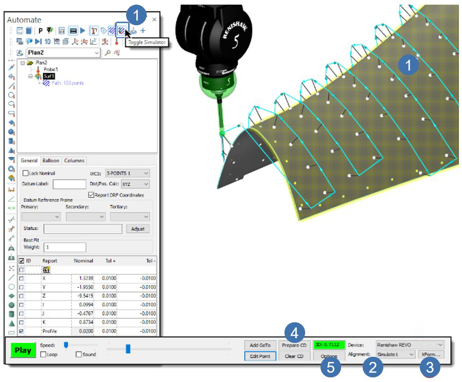
- Select Options.
- Select the appropriate Project To type based on the CAD.
- Enable what to check for collision, for example, Probe and Shaft.
- If Head is enabled, enter a diameter encompassing the probe head.
- The Clearance value applies to both the Probe and Shaft.
- The probe and shaft definition create the clearance zone.
- Select OK to accept or Cancel to disregard any changes.
- To start or pause the simulation, select Play.
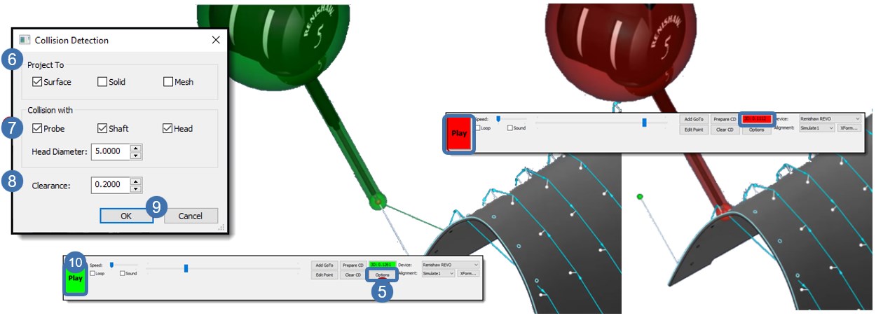
When a collision is detected, the applied Clearance zone turns green to red, indicating a crash. The Play button and 3D value also turn from green to red. The 3D value is the distance from the probe definition to the nearest CAD entity where the collision is detected.
- Pause the simulation where applicable and select Add GoTo.
- A GoTo is automatically inserted in the path, and the Edit Point dialog displays.
- The user can use the dX, dY, and dZ fields to scroll and place the GoTo position to avoid the collision or enter the desired value and select the “X” on the top right-hand side of the Edit Point dialog to accept and close.
- The scroll increment increases or decreases the GoTo moves using the arrows in the dialog or scrolling in each field with the mouse.
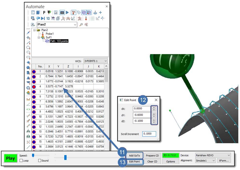
- To edit a GoTo position placed during simulation or set during the inspection planning, select Edit Point (13) when near the appropriate GoTo and use the dX, dY, dZ fields (12) to scroll and place the GoTo position. Then select the “X” on the top right-hand side of the Edit Point dialog to accept and close.