
Boom Breaks the Barrier on Enterprise Measurement Solution
It improves quality, increases speed to market, and reduces cost.
Boom Supersonic has its sights firmly set on the return of supersonic civilian air travel with the development of Overture, its 55-75 passenger, Mach 2.2 commercial airliner. As a run-up to the production model, the company has been making steady progress towards its scheduled 2020 flight testing of the 1/3 scale proof of concept called XB-1. The objectives behind development of the XB-1 are more than just real-world flight testing of this highly sophisticated aircraft, involving the latest materials and technologies. The XB-1 build is helping to determine best practices in manufacturing, quality verification, bench testing, assembly guidance, process control, and team development, all with the goal of informing the development of Overture. In the process, Boom has broken through the barrier of traditional thinking, creating model-based measurement and inspection techniques that are improving quality, increasing their speed to market and reducing cost.
When you are designing and building a commercial aircraft intended to fly Mach 2.2, or roughly 1,459 MPH, precision and quality verification of every part is critical. The culture at Boom perpetuates a can-do attitude grounded in thoughtful design, aerospace experience, and a relentless pursuit of quality. These quality and innovation tenets ingrained in the Boom brand drives the project development team to think differently about how they approach inspection and measurement, not only across the Boom enterprise, but throughout their supply chain as well.
BOOM FACTS
- Cruising altitude 60,000 ft
- Speed Mach 2.2 or approx. 1,459 MPH
- New York to London, 3hr 15 min
- San Francisco to Tokyo, 5hr 30 min
- 4,500 nm range
BUILDING THE BOOM XB-1
- Building internal team
- Building supply chain team
- Building analysis tools
- Building iterations and flight testing
- Building process control
In order to put a comprehensive measurement strategy in place, the Boom development team first considered the application objectives and scope of measurement and reporting across the enterprise. “For many engineers the term measurement or metrology is synonymous with inspection and quality verification. At Boom we are no different, but we also embrace metrology as a means to build quality into everything we do,” said Ryan Bocook, manufacturing engineering lead. The team determined they needed a wide array of measurement solutions to support the design and manufacturing process, both internally and throughout the external supply chain.
“It was our goal from the beginning to develop manufacturing techniques and processes in parallel with the production of XB-1. This required absolute documentation, process control, reporting, and solid data management from the get-go, which led us down the path of Model-Based Definition (MBD),” said Bocook.
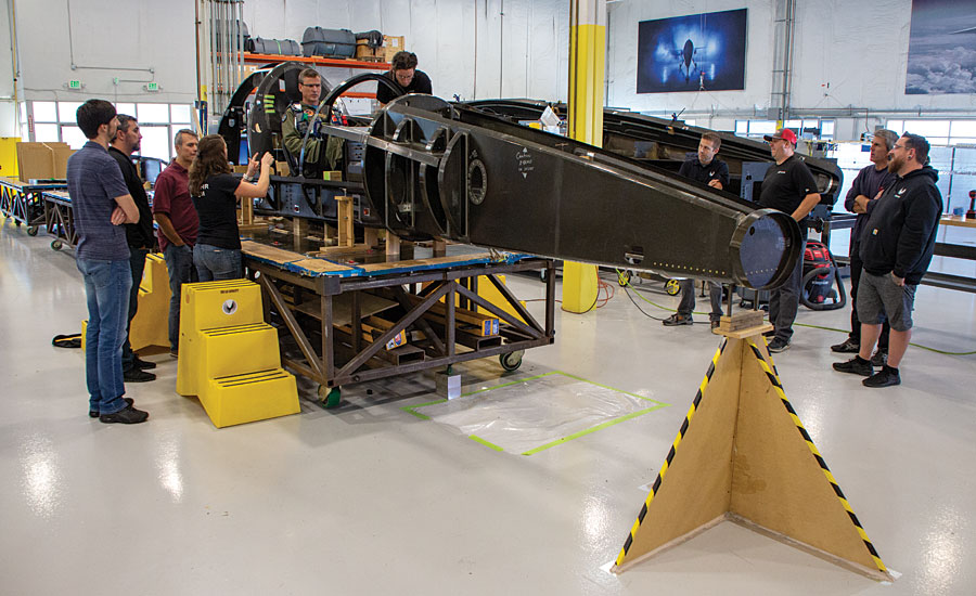
Chief test pilot, Bill Shoemaker, conducts ergonomic test in the carbon fiber, XB-1 nose bay sub assembly.
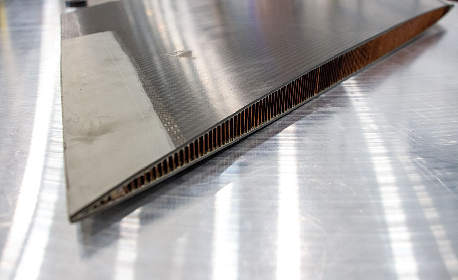
Finished horizontal composite tail section with machined core.
When deploying an MBD strategy, the 3D CAD model becomes the basis for all information necessary to manufacture a part or product and manage aspects of the product life cycle. Everything needed to produce a part is included in the CAD model, from design to manufacturing, and all Geometric Dimensioning & Tolerancing (GD&T) data. The use of MBD and its contributing counterparts, model-based measurement and inspection maintain the all-important digital thread (aka the digital twin). The use of MBD can be far reaching and include many different attributes of a given part or product, including finish, coatings, colors, version control, statistical process control (SPC), and much more. But for most parts, model-based measurement and inspection are a great place to start as they are critical to virtually all implementations of MBD. “At Boom we maintain the 3D CAD model as the authority, which removes ambiguity, conflict and doubt that arise when drawings and models co-exist. With authority bestowed on the model, MBD eliminates errors that result from referencing an incorrect source and makes processes more efficient,” added Bocook.
“For many engineers the term measurement or metrology is synonymous with inspection and quality verification. At Boom we are no different, but we also embrace metrology as a means to build quality into everything we do.”
COMMON MEASUREMENT AND INSPECTION PLATFORM
Boom’s model-based measurement and inspection strategy covers every department within the manufacturing enterprise, including design, manufacturing, shipping/receiving, assembly, and quality inspection. In order to effectively manage the breadth of measurement and inspection needs, Boom determined the following solution requirements:
- A single measurement software needs to drive all metrology processes, including quality inspection, reverse engineering, tool building, and assembly guidance
- Software must interface with and control a variety of portable measurement devices, including arms and trackers
- Software must be model-based on a CAD platform for flexibility in managing files, creating and executing model-based inspection
- Software must be able to import and allow editing of intelligent GD&T data to quickly create inspection routines
- Software must handle a range of inspection data, from manual probing to noncontact scan data
The use of MBD and its contributing counter parts, model-based measurement and Inspection maintain the all-important digital thread (aka the digital twin).
APPLIED MEASUREMENT
The old adage “If you can’t measure it you can’t monitor it” holds true at Boom. Virtually every part is subjected to quality verification—100% inspection. “We are using measurement and inspection software all over this aircraft, I doubt there is a single part that hasn’t been probed or scanned,” said Wyatt. Boom uses model-based measurement and inspection in new and creative ways to effectively shave hours, days, and weeks off critical processes while actually improving on the end results. Model-based measurement and inspection is a critical component in designing, reverse engineering, inspecting and scanning of flight hardware and test articles, including:
- Inspection of Tooling and Finish Parts
- Reverse Engineering
- Tooling Design and Validation
- Off Aircraft Test Setup
- On Aircraft Part Locating
INSPECTION OF TOOLING AND FINISH PARTS FROM SUPPLIERS
Custom flight hardware requires dimensional inspection of critical features. Boom uses model-based inspection software to verify incoming parts as well as validate first article inspection reports provided by suppliers. This can be machined components, composite parts and assemblies, tooling, sheet metal, 3D printed metallics, or virtually any other internally produced or outsourced part.
“We are using measurement and inspection software all over this aircraft, I doubt there is a single part that hasn’t been probed
or scanned.”
Composite tooling inspection and part validation using Verisurf software.
Inspection of incoming composite tool using Verisurf software.
Boom selected Verisurf Software because of its open CAD-based architecture, model-based capabilities and its ability to work with and drive virtually all hardware measuring devices. “Verisurf software serves as a common measurement platform for Boom and communicates openly with all our CAD files and those used by our vendors,” said Todd Wyatt, metrologist. “We realize improved quality and efficiency while reducing our direct cost by standardizing on a common platform. All our users are trained on a single measurement and inspection software and we are only supporting one software from a licensing, data management, and maintenance point-of-view,” added Wyatt.
REVERSE ENGINEERING
In order to reduce schedule time to build XB-1, many parts are COTS (Common Off the Shelf) components utilized from other aircraft builds. For example, the engines are GE J-85-15 engines. Boom did not have a good model of critical interface points, so the measurement software was used to reverse engineer locations of features such as: engine mounts, gear drive shaft, fuel manifolds, and air ducting. By scanning the exterior of the engine, a basic clearance model was made for bulkheads, nacelles and other systems to ensure proper fit in tight spots.
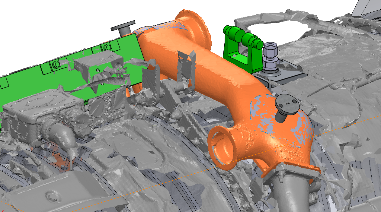
Reverse engineered ducting and mounting assembly using Verisurf software.
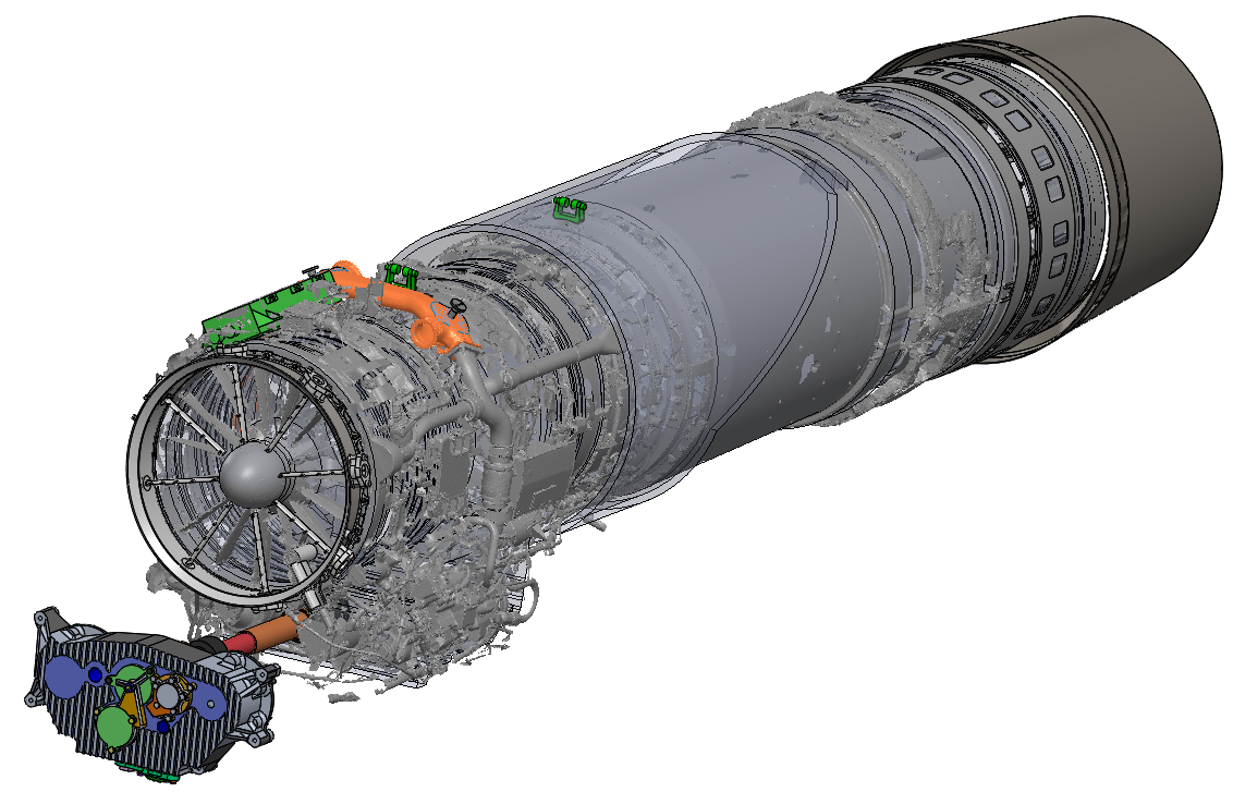
Reverse engineered engine assembly model using Verisurf software.
TOOLING DESIGN AND VALIDATION
Due to the one-off nature of XB-1, tooling needs to be generated quickly and at low cost. With the aid of measurement software for reverse engineering, a part or surface can be scanned or probed, and a custom part/tool can be designed around the collected data. For example, in order to disassemble an actuator, special tools are required. Scanning or probing allows for the quick capture of the dimensions required to design and build a tool. Paired with 3D printing, tools can be designed and generated in a matter of hours. Much of the XB-1 structure is made from composite material; the measurement and inspection software is used to compare composite tooling to the 3D CAD model prior to layup.
Horizontal tail test fixture model using Verisurf software.
Pitch actuation test fixture model using Verisurf software.
BEST FIT ANALYSIS
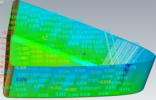
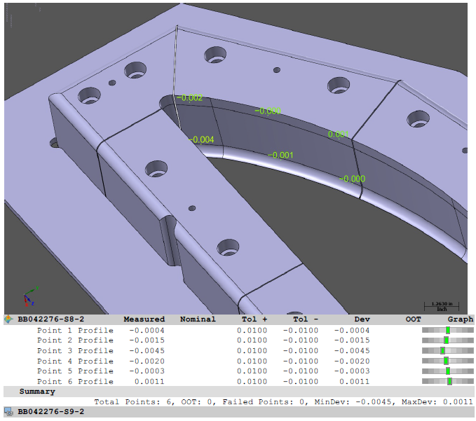
A good example of a one-off composite part build for XB-1 is the horizontal tail (HT) assembly. Measurement software played a critical role in creating custom surfaces based off actual manufacturing tolerances. The process to build the HT assembly consisted of:
- The upper skin of the horizontal tail was laid up in the tool.
- The B side of that composite skin was scanned while in a vacuum chuck holding the part contour to the tool.
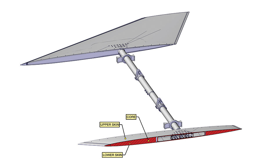
Verisurf software used for best fit analysis to create intelligent CAD model used to machine core that fits within envelope.
- The measurement software was used to create NURBS surfaces of the actual produced B side of the composite part.
- The NURBS surface was then used to trim the core model to the actual scan and a CNC program was generated for machining of core to match the actual part profile.
- The machined core was then bonded to the outer skin B side.
- The lower skin was laid up and scanned.
- In the same fashion as the outer skin process, the scans of the actual part is then used to machine the bonded core to match the closeout skin exactly.
- Finally, the close out skin can be bonded, and the horizontal tail sandwich construction is near complete.
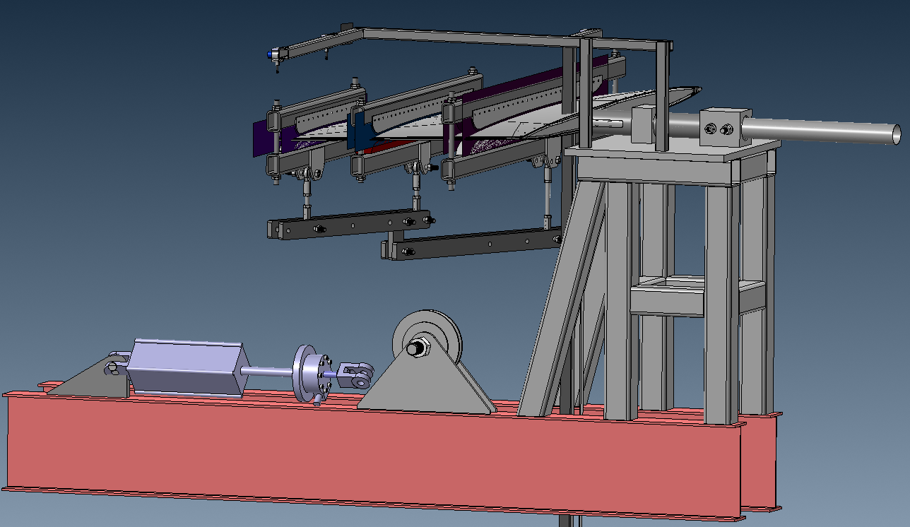
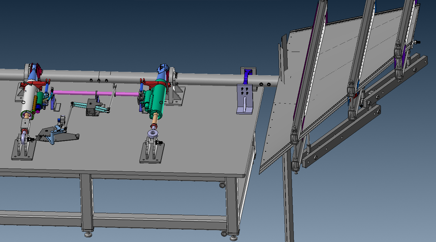
OFF AIRCRAFT TEST SETUPS
To support and validate engineering design for XB-1, several off-aircraft test rigs were designed and built. Using a bench setup, model-based measurement software is used to locate components prior to welding/fixing and to validate that the critical components in the rig assembly are aligned properly. For example, the horizontal tail torque tube axis precisely aligned using the measurement software and welded in place during setup. Similarly, the pitch rig, which includes several parts located in 3D space, are accurately aligned and welded in position. The aileron test rig was also set up using the measurement software to locate all parts per the CAD model.
ON AIRCRAFT PART LOCATION
Model-based measurement software is critical in locating XB-1 structures and parts in 3D space. Because XB-1 is a one-off build, assembly tooling needs to be simple and inexpensive. The measurement software aids in this mission by eliminating the need for precise assembly fixtures and allowing for flexibility in installing components in 3D space. The software uses laser trackers and arms to precisely locate and place parts into position during assembly. There are several examples where this application is critical to the build, including composite structural assembly, locating the wing subassembly to the fuselage body, and locating systems parts and brackets in the fuselage.
Using laser trackers, CAD model-based measurement is used for wing positioning during final assembly. This method provides precise assembly guidance without the time and cost associated with building assembly fixtures.
“Model-based measurement and inspection software plays a critical role in the fabrication and assembly of XB-1, from part inspection, to tooling, setup and validation, to reverse engineering, creating fixtures, and ultimately the assembly of the aircraft. Today’s measurement software is easy to use and easy to learn; it has found its way into virtually every design/build process at Boom,” said Wyatt. “Without it the aircraft build would be slower, more expensive and less precise.”
Verisurf Software, Inc.
Verisurf Software, Inc. is a measurement solutions company, committed to delivering advanced surface analysis, quality inspection, assembly guidance, and reverse engineering. Verisurf products and processes are vital to maintaining a digital thread between design, engineering, manufacturing, and finished part validation. Based on a powerful CAD platform, Verisurf is committed to digital Model-Based Definition (MBD), open standards, and interoperability with all coordinate measuring machines and CAD software. Verisurf solutions help manufacturers produce higher quality products in less time. For more information visit https://verisurf.com.