
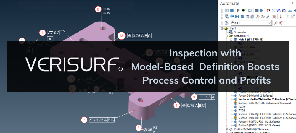
Inspection with Model-Based Definition Boosts Process Control and Profits
Inspecting manufactured products to confirm compliance with engineering specifications and subcontract obligations can be burdensome, but it is nonetheless necessary. Adopting a closed-loop, fully digital thread through all aspects of the product lifecycle offers the highest level of process control and even presents the 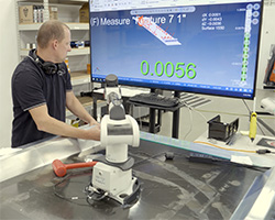 opportunity to improve margins. Establishing a modern approach by designating the 3D CAD model as the controlling authority for product definition is what Model-Based Definition (MBD) is all about. For the resource-consuming inspection aspects of the product stream, whether it be first-article inspection (FAI), in-process checks, or regular recurring quality control inspection, utilizing embedded and interactive product manufacturing information (PMI) and geometric dimensioning and tolerancing (GD&T) will ensure the modern enterprise can reap MBD’s benefits.
Getting Connected for Model-Based 3D Measurement
To take advantage of model-based definition, many manufacturers need only to enable investments they have already made. It might require a small purchase of hardware or software, but it should not require a significant financial outlay to start reaping benefits. Many companies already have some type of CMM or portable coordinate measuring devices; others will want to make at least a small investment in 3D measuring technology. It does not have to start with a significant change in practices, nor does it require massive commitment, stoking fears of future regret or wasted resources. It simply takes a CMM (coordinate measuring machine) or other computer-aided inspection (CAI) system powered by software that takes advantage of the PMI within the CAD model. PMI that is associative, and not simply “dumb” text, is sometimes referred to as semantic PMI. GD&T is one of the main components of PMI. When it comes to 3D measurement, it is the GD&T within PMI that is relevant. It includes tolerances, reference datums, and other inspection rules and constraints. For it to be usable by the CAI metrology software, it must be connected operationally to features, and not simply displayed onscreen as a textual note.
MBD works as “interactive GD&T” bridging the gap between CAD and computer-aided inspection, yielding many productivity and process control benefits.
Benefits of Computer-Aided Inspection (CAI)
Measuring things like aircraft wings or airfoils, automobile body panels (body-in-white – BIW), or curvy molded parts, calls for 3D inspection to CAD using one of many varieties of CMM. Complex contours not definable by mathematical or geometric features must be verified by inspection against the CAD definition because measuring them with micrometers, calipers, height gages, or dial indicators is not feasible. For these types of measurements, CMMs are a must, and this is where they stand out as essential inspection systems. However, we should note that even for geometric features, you can speed up inspection when the CAD model defines nominal dimensions. It further reduces errors from manual transposition of numbers and ensures a cohesive, digital process for a highly controlled inspection methodology. We will include nominal values, profiles, and feature locations to embrace the full potential, taking advantage of model-based tolerances, datum referencing, and GD&T relationship callouts.
The Challenge – Non-Digital, 2D Data, and PMI That Can’t be Engaged from the 3D Model
Computer-aided design, a.k.a. CAD, has been around for decades now. Products are designed using 3D CAD software platforms, from which there are many to choose. The 3D model is used not only for design but also for research and development, subcontracting and customer collaboration, manufacturing processes such as CNC and additive manufacturing, and computer-aided inspection. For complex contours, the need to inspect surface profile and hole position to CAD is inescapable. Nonetheless, ancillary means of product definition remain for lots of reasons. For many years, non-CAD definition continued to be necessary for verification and control of geometry as well as for assemblies. Examples are two-dimensional drawings or blueprints, check fixtures, wooden “master models” that were predominant in aerospace, and the “Meisterbock” common in automotive manufacturing.
 As time proved, disparities between physical product definition and digital models became a problem of process control, quality assurance, and safety, especially in aerospace and automotive applications. The term “model-based definition,” or MBD, was initially aimed at setting standards to designate a single source as “the final authority” of legitimate product definition. Where there was disagreement, the 3D model was to be the approved design authority. The concept also seeks to remove the potential for disparity that might arise from using more than one form of product definition by going to a single source, the 3D model. However, since it is unavoidable at times, MBD gives the CAD model priority over everything else.
The Solution – Model-Based Definition: Integrated and Useable PMI Data from CAD
It is possible to employ a CAD model with associative PMI so it can be applied interactively in computer-aided inspection. Some metrology software can use the PMI directly, automatically applying it to the inspection of features and CAD surfaces in the model. When no PMI exists in the model, some metrology software can easily add PMI, making it semantic and automatic for tolerances, GD&T callouts, and reporting. With usable and connected PMI employed by the metrology software, any connected 3D measurement system can reap the benefits, allowing for improved productivity and process control. By eliminating the need to refer to 2D drawings or extract information from textual but non-associative GD&T in the model, time is saved, complexity is reduced, and transposition errors are avoided. Engaging this fully connected digital thread is the essence of MBD.
CMMs both Fixed and Portable Can Employ MBD/PMI During Programming and Live Inspection
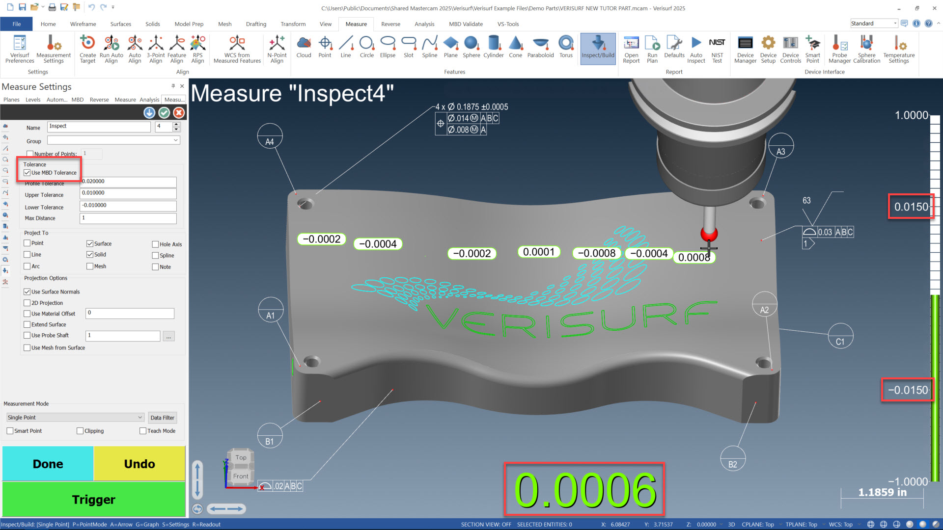
Verisurf allows automatic use of MBD/PMI for live onscreen feedback during inspection. The model will employ PMI from the CAD model for profile and position tolerances, giving inspectors real-time indication of in or out of tolerance conditions.
Process Control Improvements for both Quality Control and Manufacturing Systems
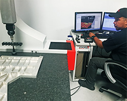
Manufacturers that incorporate MBD for inspection gain improved process control for their metrology lab and QA department by closing the loop and automating the connection of tolerancing and measurement constraints, as mentioned above. The inspection process becomes seamless and streamlined, reducing wasted time, errors, and the burden of keeping track of and maintaining disassociated documents. The most beneficial is the clean and controlled workflow throughout the process of inspection and reporting. Removing ambiguities and ensuring that consistent methodology and best practices are used and that every part is checked precisely the same way every time ensures a high level of control over the QA process.![]()
By working with a digitally connected and better-controlled inspection and QA process, the entire enterprise, up and down the product lifecycle chain, benefits from better process control within each aspect. It has been said that it’s hard to control a process that isn’t measured. And one can conclude that refined and better-controlled measurement practice can enable more control of other interrelated processes.
QA Inspection Workforce Challenges Diminished
Understanding 2D drawings with complex GD&T and applying the principles correctly for inspection can be daunting. And it requires a lot of training, skills, and experience. Using hand tools such as dial indicators, gage blocks, micrometers, and calipers requires skill and experience to be effective and productive. However, with embedded and automatically applied MBD, manual CMMs can be operated simply by following onscreen indicators and instructions. For motor-driven, programmable CMMs, visual click-drag-scroll, “no-code programming” is also greatly simplified, modernized, and streamlined.
With MBD-enabled digital measuring, the organization can use operators with minimal training and experience, minimizing what it takes to make operators productive and virtually mistake-free. This approach makes it easier to find the right people and keeps them engaged with a more modern process that rewards the user with a “job well done” under much less stress than old-school methods.
Embracing MBD
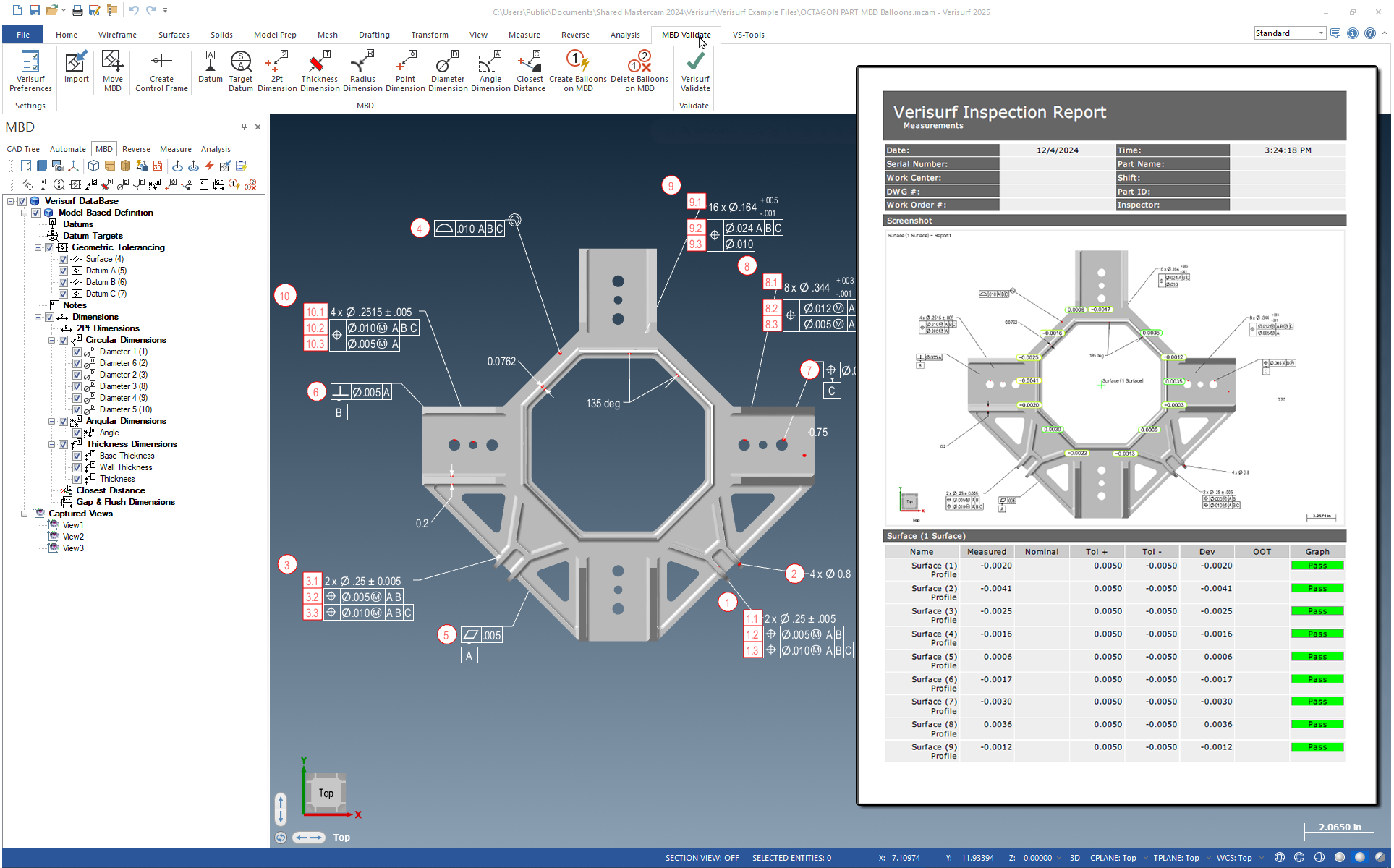
Metrology Software Creates Inspection Plan from PMI
Verisurf software provides automatic inspection plan creation from MBD/PMI, applicable for both motorized stationary CMMs and manual, portable CMM arms, trackers, and scanners. Not only does it create the inspection features and applies tolerances, it also creates CMM paths for the features automatically.
MBD in Quality Control Changes Metrology from Cost Burden to Profit Booster
Business owners often see QA metrology as a necessary evil, as a cost center, not a profit center like their production machines. Upon enterprise-wide implementation of MBD, organizations can lower costs, cut production cycle time, reduce scrap, and improve workforce development and employee retention.
Glossary
ASME–American Society of Manufacturing Engineers
CAD–Computer Aided Design
CAI–Computer Aided Inspection
CMM–Coordinate Measuring Machine
FAI–First Article Inspection: A manufacturing and quality assurance process to satisfy product specifications and quality requirements before full production begins.
GD&T–Geometric Dimensioning and Tolerancing: Drawing dimensions and tolerance callouts that define controls for design, measurement, and verification of geometry and features on the drawing or 3D model which control form, fit, and function of the part or assembly. The ASME Y14.5 specification provides rules and definitions approved by the ASME committee. (International similar standards–ISO GPS is a general term for several specifications covering GD&T)
GPS–Geometrical Product Specifications (ISO)MBD–Model Based Definition: The engineering and manufacturing process that designates the 3D CAD model as the controlling authority for product definition, superseding all other means such as 2D blueprint drawings, master models, mylars, PDFs, etc.
ISO–International Standards Organization
PDF–Portable Document Format
PMI–Product Manufacturing Information
QA–Quality Assurance
Author: Scott Knoche – Verisurf Software, Inc. (technical marketing & sales at Verisurf since 2002)