
Verisurf MBD
Create functional 3D GD&T on CAD models and apply imported GD&T automatically to your inspection and reporting workflows for the ultimate in process control.
Verisurf MBD (model based definition) allows you to create or import and edit CAD models with ASME Y14.5-compliant GD&T from PMI (product manufacturing information) or FTA (functional tolerancing and annotation) including manufacturing data, dimensions, tolerances, and engineering notes. Semantic tolerances for GD&T Profile and Position callouts as well as Datum Targets can be automatically applied in live inspection, CMM programs, tolerance analysis, and QA reports. Powerful dimensioning tools that are easier to use than typical CAD tools, make it simple to add dimensions, angles, thicknesses, and more to aid in viewing and reporting.

Automatically add AS9102/PPAP inspection balloons to dimensions and callouts

Create GD&T control frames visually and functionally linked to CAD features

Provide model-based, interactive GD&T that is applied during real-time inspection as well as in CMM programs and report output

Frequently needed dimensions such as distance, angle, diameter, thickness, etc., easily created for viewing and reporting

Unique graphical display of text and symbols always facing forward making them easy to read in screenshots and reports

Datum targets may be automatically used for functional, precise, model-based alignments for superior process control
GD&T Callouts
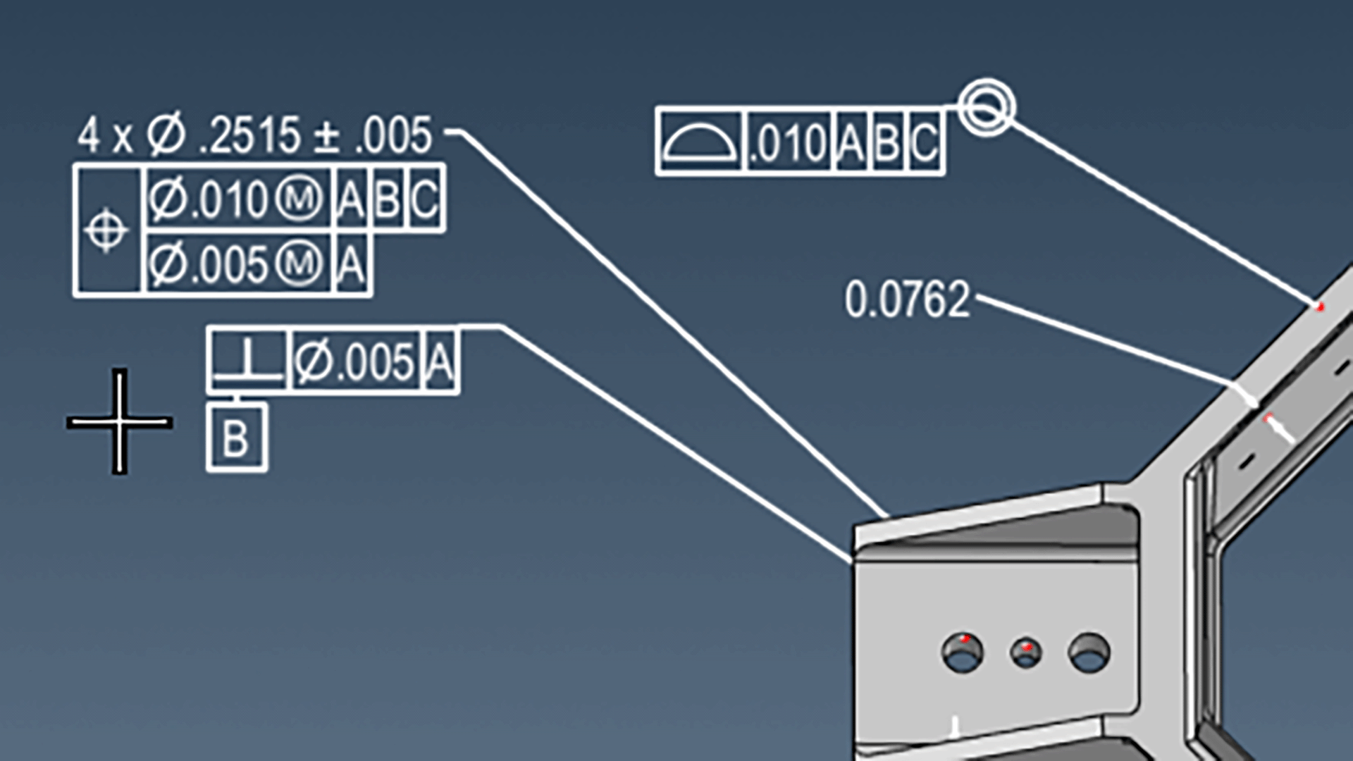
- Create GD&T control frame (callouts) with nominals, tolerances, modifiers, datum references, etc
- MBD/GD&T is functional and CAD feature associative for Profile and Position
- Callouts are hotkey resizable for better viewing and screenshots
User-Facing Annotations
- MBD remains screen forward and user-facing for better viewing, screenshots, and reports
- Text, annotations and symbols maintain a fixed size even when zoomed in or out
- Hotkeys easily toggle annotation scale/size up and down
Add/Import Dimensions
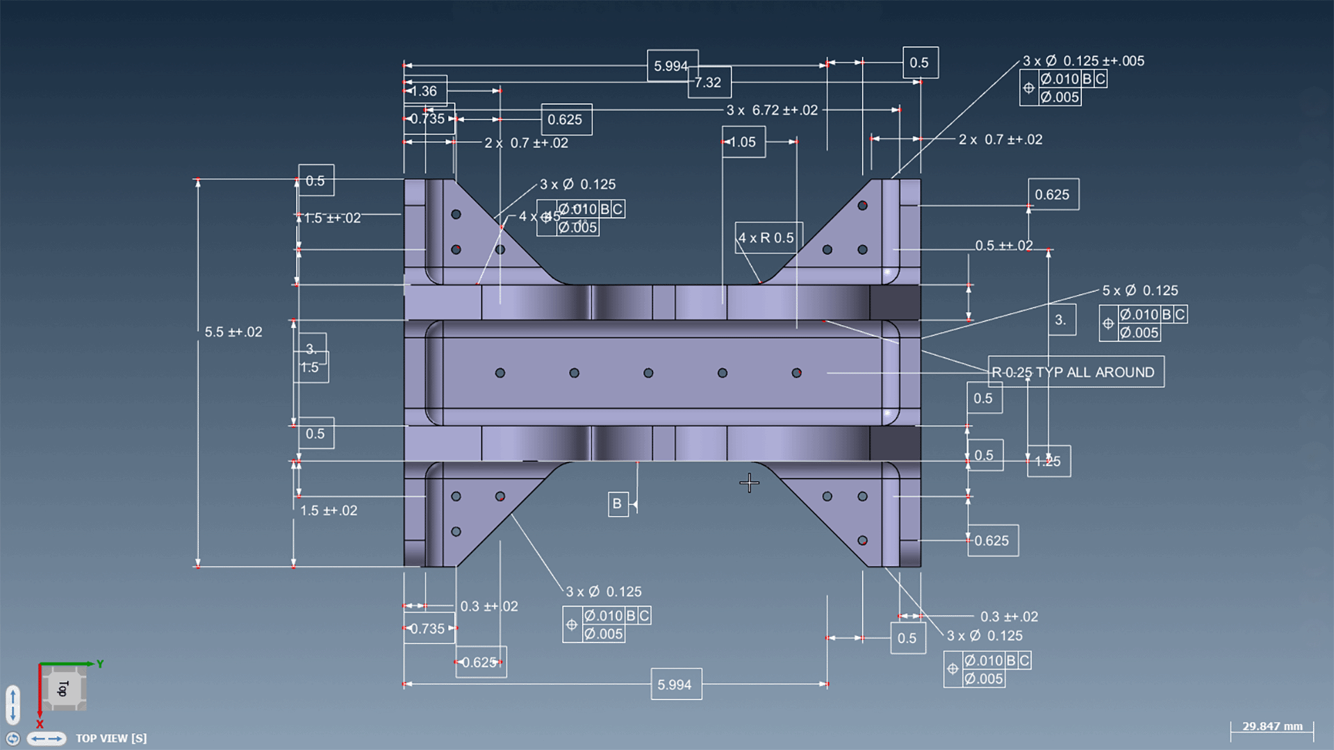
- Create accurate dimensions from easily and reliably selectable anchor points
- Forward-facing text that is hotkey resizable with for clarity
- Import dimensions from compatible, native CAD files such as CATIA
Interactive GD&T
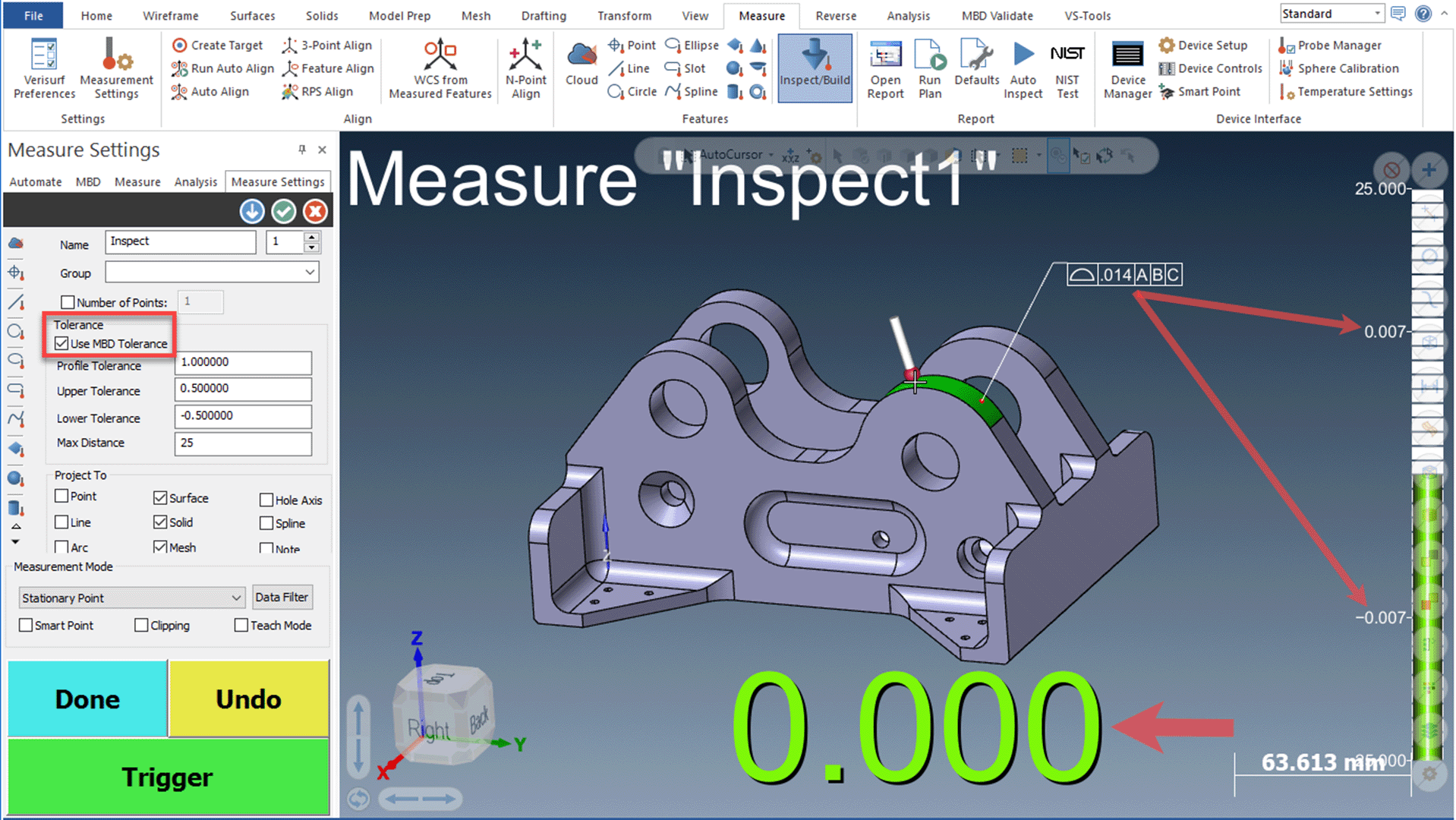
- MBD is enabled as “interactive GD&T” which sets tolerances for Profile and Position
- In Verisurf live BUILD/INSPECT mode MBD tolerances are applied in real-time display of in or out of spec, reflected in informative color and sound feedback
Automatic Datum Alignment
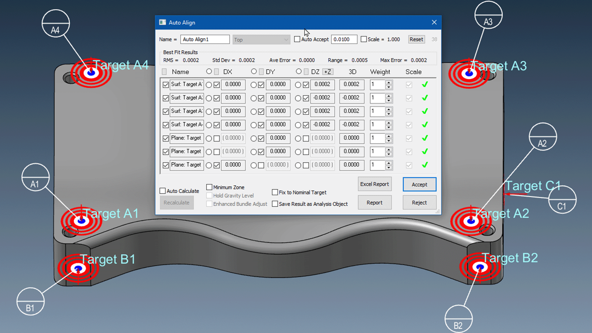
- MBD Datum Targets may be used for Verisurf’s powerful AUTO ALIGN
- Datum targets create an automatic, precise, model-based alignment
- Alignment from datum target specific locations provide repeatability and superior process control
Gap & Flush Measurement
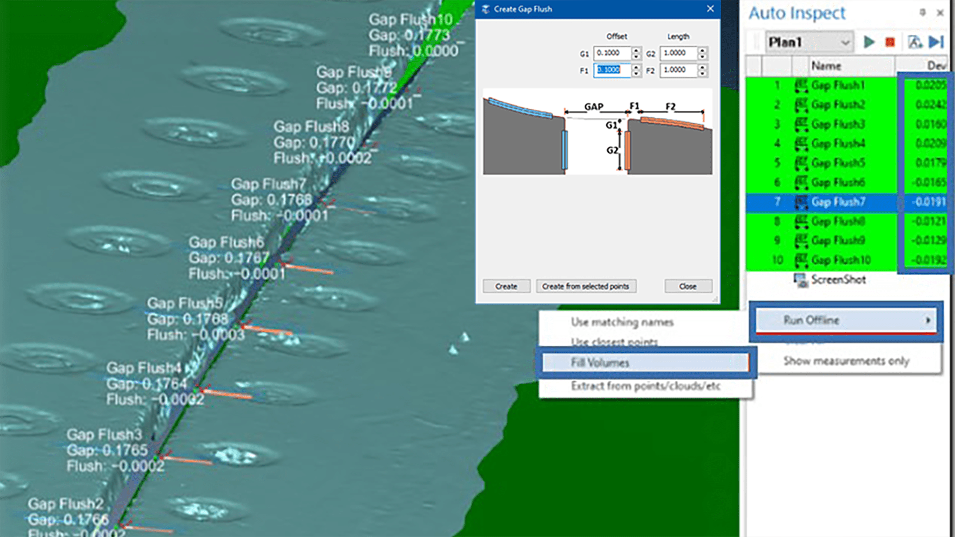
- Set gap & flush callouts for display as part of MBD
- Creates the nominal locations and values for gap & flush inspection
- Gap & flush MBD is used to create and then measure via automated inspection plans, ideal for scanned pointclouds and meshes
Captured Views
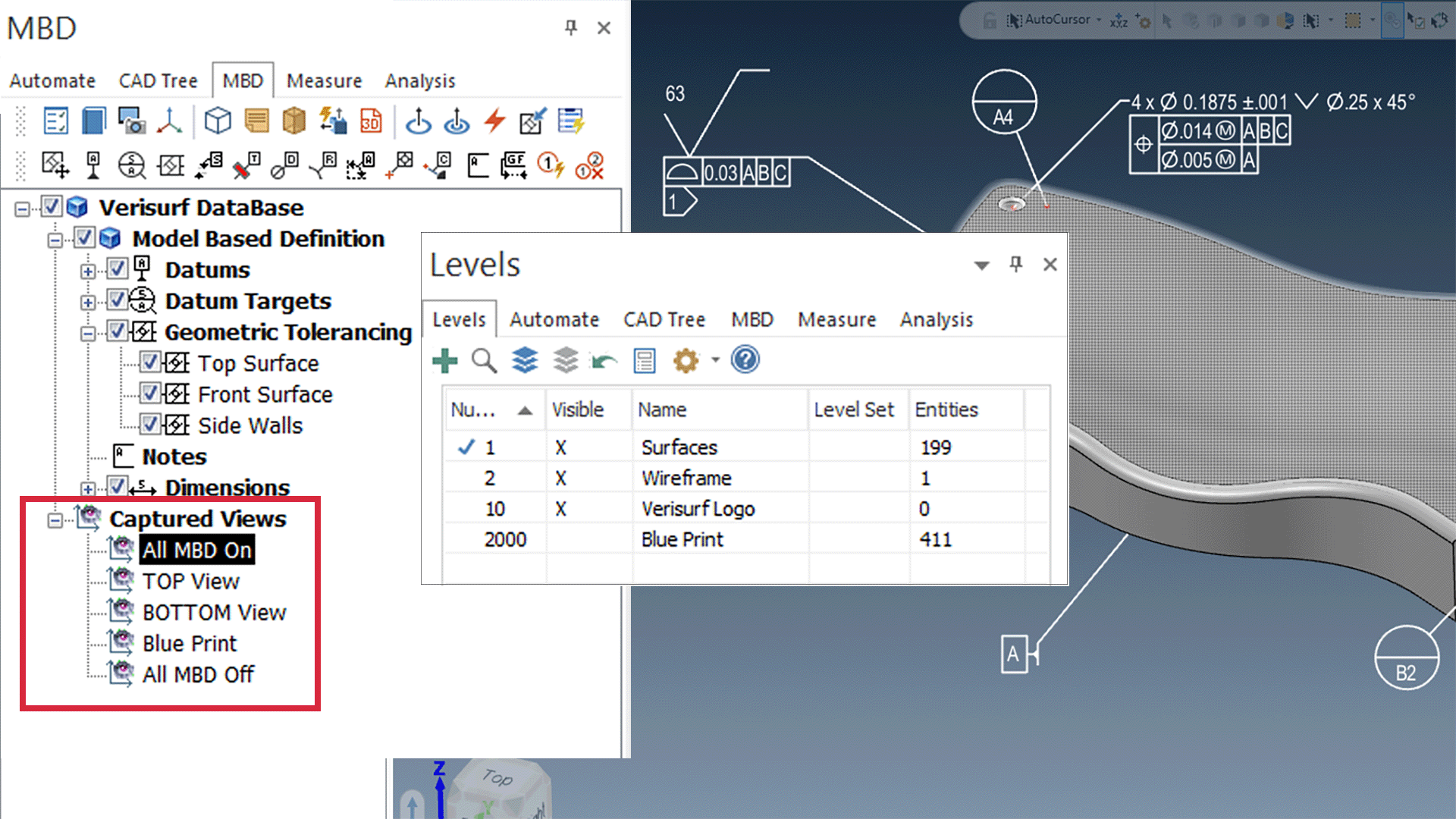
- Allows one-click toggle of CAD levels/layers and MBD on/off states to quickly change what’s on the screen
- A significant productivity tool that eliminates excessive mouse clicks and hunting for the desired view of the model
- Captured Views can be imported from native CATIA models
Automate CMM Programming
- Use imported MBD (GD&T, PMI, FTA) to create a CMM or automated inspection program
- Automatically utilizes the nominals and tolerances from the model
- Datums assigned from MBD
Automatic AS9102/PPAP Balloons
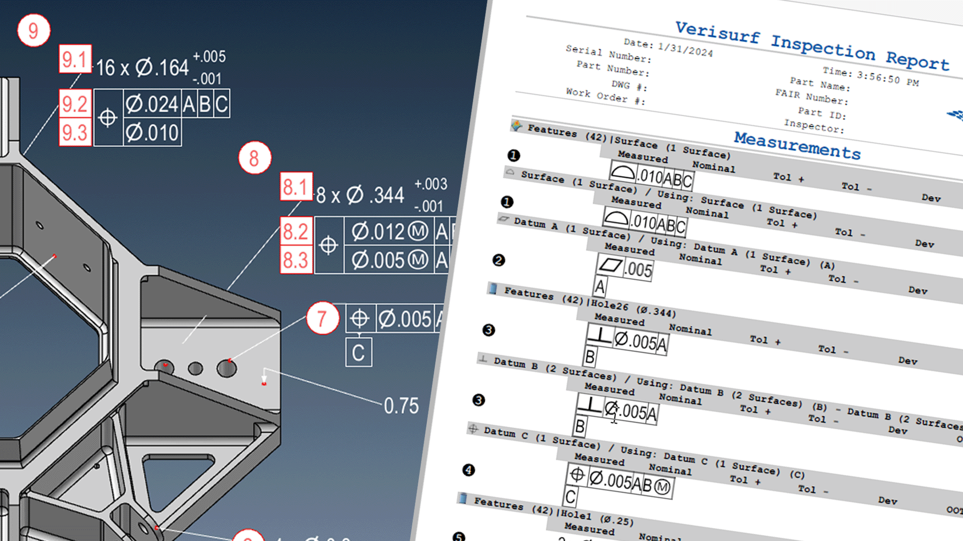
- One-click addition of inspection balloon IDs to dimensions and GD&T callouts
- Quick and easy setup for AS9102 and PPAP reports
- Balloon IDs carry over to inspection reports and CMM programs
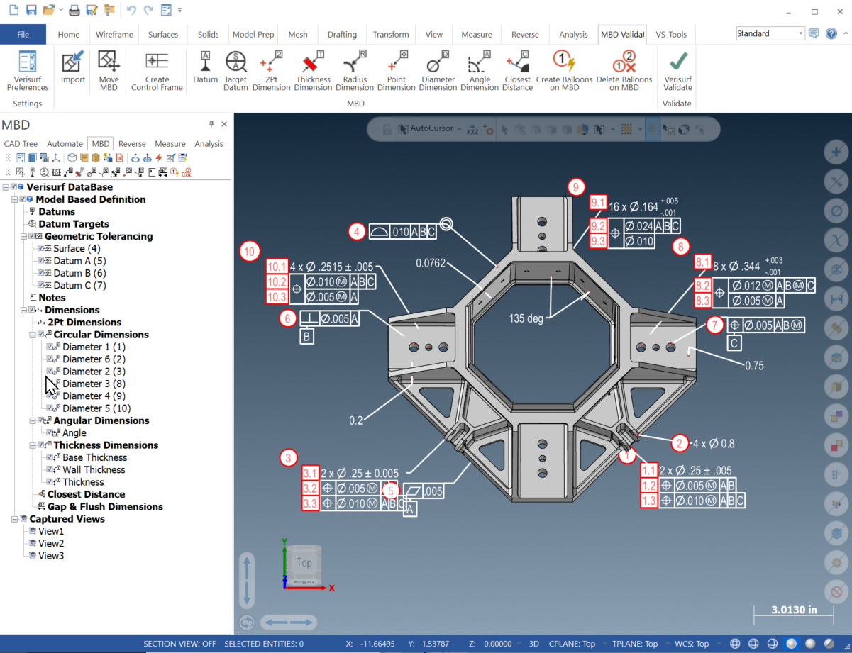
The Verisurf Model-Based Definition (MBD) Manager includes all of the Tools and Utilities listed below. MBD annotations appear in the Operations Manager tree and in the graphics area and can easily be added, edited, or deleted.
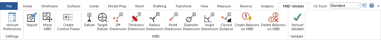

Reposition an existing MBD callout frame.

Label a feature as a datum.

Label a feature with a datum target.

Control frame – assign an MBD (GD&T) callout to a feature.

Apply a distance dimension between 2 points or parallel planes.

Apply a dimension to a part thickness.

Apply a dimension to hole diameters.

Apply a hole radius dimension.

Apply a dimension between planar and angular surfaces.

Dimension a point coordinate.

Display the shortest distance between a point and a CAD surface.

Place an annotation without a leader to a feature.

Use surfaces or CAD points to define Gap and Flush dimensions.

Open Verisurf Preferences – Display Settings dialog.

Open the MBD Reference Manual.

Screenshot – Capture graphics window images to be used in the Report Manager or Microsoft Paint.

Remove hidden lines to improve the clarity of MBD callouts.

Create a circle from a hole.

Add model-specific (Part) notes or general notes that persist across all models.

Minimum Bounding Box; used to assess minimum material required for machining.

Flip and correct Surface Normal direction for Inspect/Build or Surface Analysis.

Create a 3D PDF file that includes MBD callouts, Datum Targets, and Analysis results.

Create hole axes, vectors, arcs, or points on all visible circular entities.

Select a surface – including contiguous surfaces.

Toggle display of the WCS axis symbol at the WCS origin.